
Phase optimization apparatus and method for obtaining maximum extinction ratio in mach-zehnder interferometer wavelength converter using cross phase modulation of semiconductor optical amplifier

a wavelength converter and phase optimization technology, applied in the direction of optical waveguide light guide, optical elements, instruments, etc., can solve the problems of phase difference, limited information connection between networks that use different wavelengths, and the number of wavelengths that may be used for each channel in the network,

Inactive Publication Date: 2007-08-07
SAMSUNG ELECTRONICS CO LTD
View PDF12 Cites 6 Cited by
  • Summary
  • Abstract
  • Description
  • Claims
  • Application Information

AI Technical Summary

Benefits of technology

[0022]Additional aspects and / or advantages of the invention will be set forth in part in the description which follows and, in part, will be obvious from the description, or may be learned by practice of the invention.

Problems solved by technology

However, an information connection between networks that use different wavelengths, or the number of wavelengths that may be used for each channel in the network, is limited.
Accordingly, wavelength collision occurs when different channels use the same wavelength, and the designation of a path for each wavelength and effective routing become difficult, which may cause problems in the network system.
Furthermore, the phase difference must be stabilized because it is very sensitive to the external environment.

Method used


Image

  • Phase optimization apparatus and method for obtaining maximum extinction ratio in mach-zehnder interferometer wavelength converter using cross phase modulation of semiconductor optical amplifier
  • Phase optimization apparatus and method for obtaining maximum extinction ratio in mach-zehnder interferometer wavelength converter using cross phase modulation of semiconductor optical amplifier
  • Phase optimization apparatus and method for obtaining maximum extinction ratio in mach-zehnder interferometer wavelength converter using cross phase modulation of semiconductor optical amplifier

Examples


first embodiment

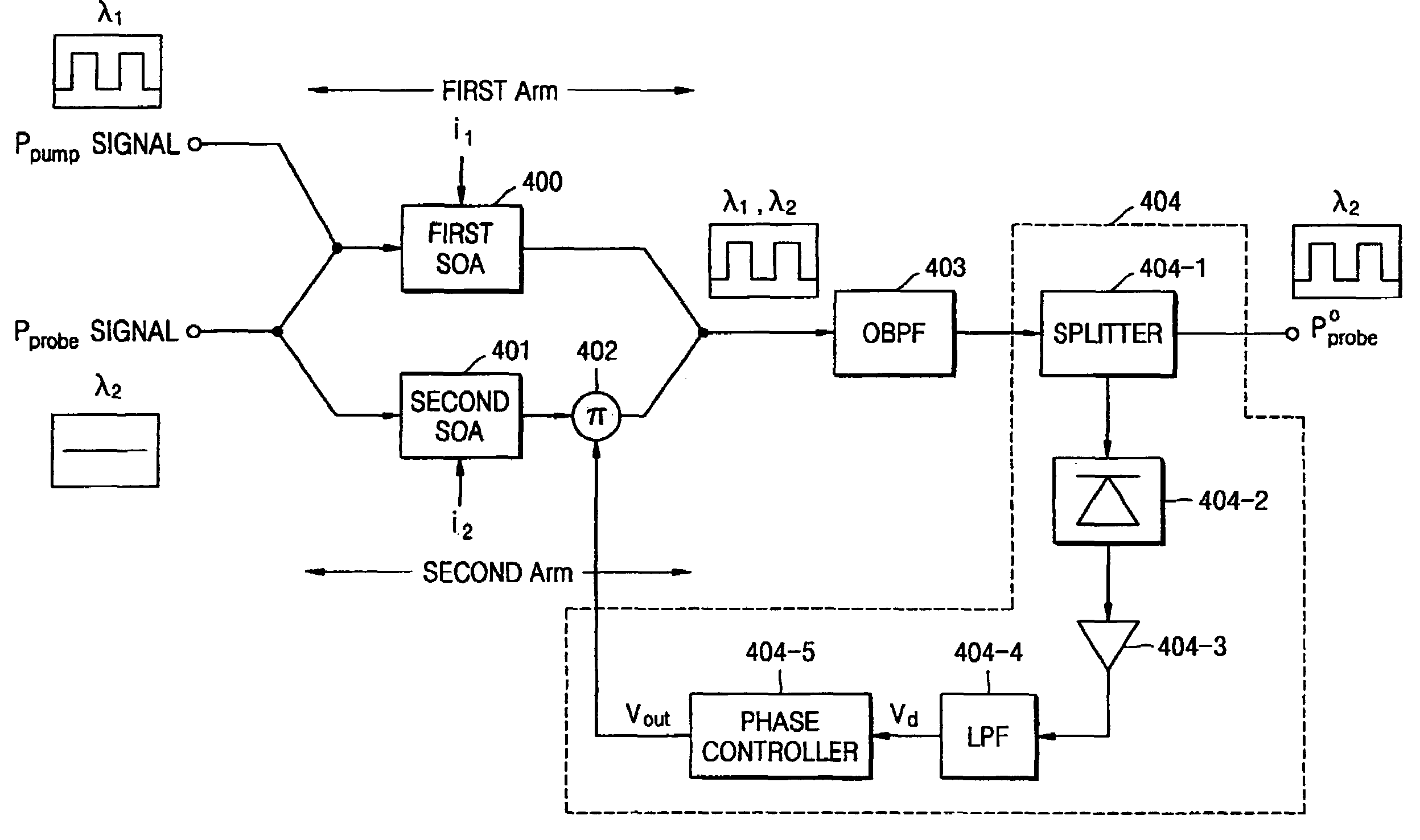
[0080]Next, a phase optimization method for obtaining a maximum extinction ratio in a Mach-Zehnder interferometer wavelength converter using XPM of a semiconductor optical amplifier according to the present invention will be explained in detail with reference to FIG. 9.

[0081]In operation 900, the phase controller 404-5 sets an initial value Vref and resolution value Δp in consideration of the operational range of the π phase shifter 402. Here, the resolution value Δp means the magnitude of phase shifted by the π phase shifter 402.

[0082]In operation 901, the phase controller 404-5 sets the first phase control signal Vout1, which is output to the π phase shifter 402, as Vref. Then, in operation 902, the phase controller 404-5 subtracts Δp from the first phase control signal Vout1 to obtain the second phase control signal Vout2 and outputs it to the π phase shifter 402.

[0083]The π phase shifter 402 shifts the phase of the output signal of the second arm according to the second phase co...

second embodiment

[0091]Next, a phase optimization method for obtaining a maximum extinction ratio in a Mach-Zehnder interferometer wavelength converter using XPM of a semiconductor optical amplifier according to the present invention will be explained in detail with reference to FIG. 10.

[0092]In operation 1000, the phase controller 404-6a sets an initial value Vref and resolution value Δp in consideration of the operational range of the π phase shifter 402. Here, the resolution value Δp means the magnitude of phase shifted by the π phase shifter 402.

[0093]In operation 1001, the phase controller 404-6a sets the first phase control signal Vout1, which is output to the π phase shifter 402, as Vref. A signal that is input to the phase controller 404-6a after Vref is set will be Vd=VPH-VBH.

[0094]The phase controller 404-6a subtracts Δp from the first phase control signal Vout1 to obtain the second phase control signal Vout2 and outputs it to the π phase shifter 402, in operation 1002.

[0095]The π phase sh...

third embodiment

[0122]FIG. 12 is a block diagram of a phase optimization apparatus for obtaining a maximum extinction ratio in a wavelength converter using XPM of a semiconductor optical amplifier according to the present invention. The apparatus includes a first semiconductor optical amplifier 1200, a second semiconductor optical amplifier 1201, an optical band-pass filter 1202, and a phase control unit 1203. The phase control unit 1203 includes a splitter 1203-1, a photo-diode 1203-2, an I / V amplifier 1203-3, a low-pass filter 1203-4, a phase controller 1203-5, and a V / I converter 1203-6.

[0123]The first semiconductor optical amplifier 1200, which operates with current i1, amplifies a pump signal Ppump and a probe signal Pprobe input thereto and shifts phases of the signals according to XPM. Here, the pump signal is a modulated optical pulse signal having a wavelength λ1 and the probe signal is a continuous wave optical signal having a wavelength λ2. The part of the phase optimization apparatus th...


PUM

PropertyMeasurementUnit
phase optimizationaaaaaaaaaa
currentaaaaaaaaaa
phaseaaaaaaaaaa

Abstract

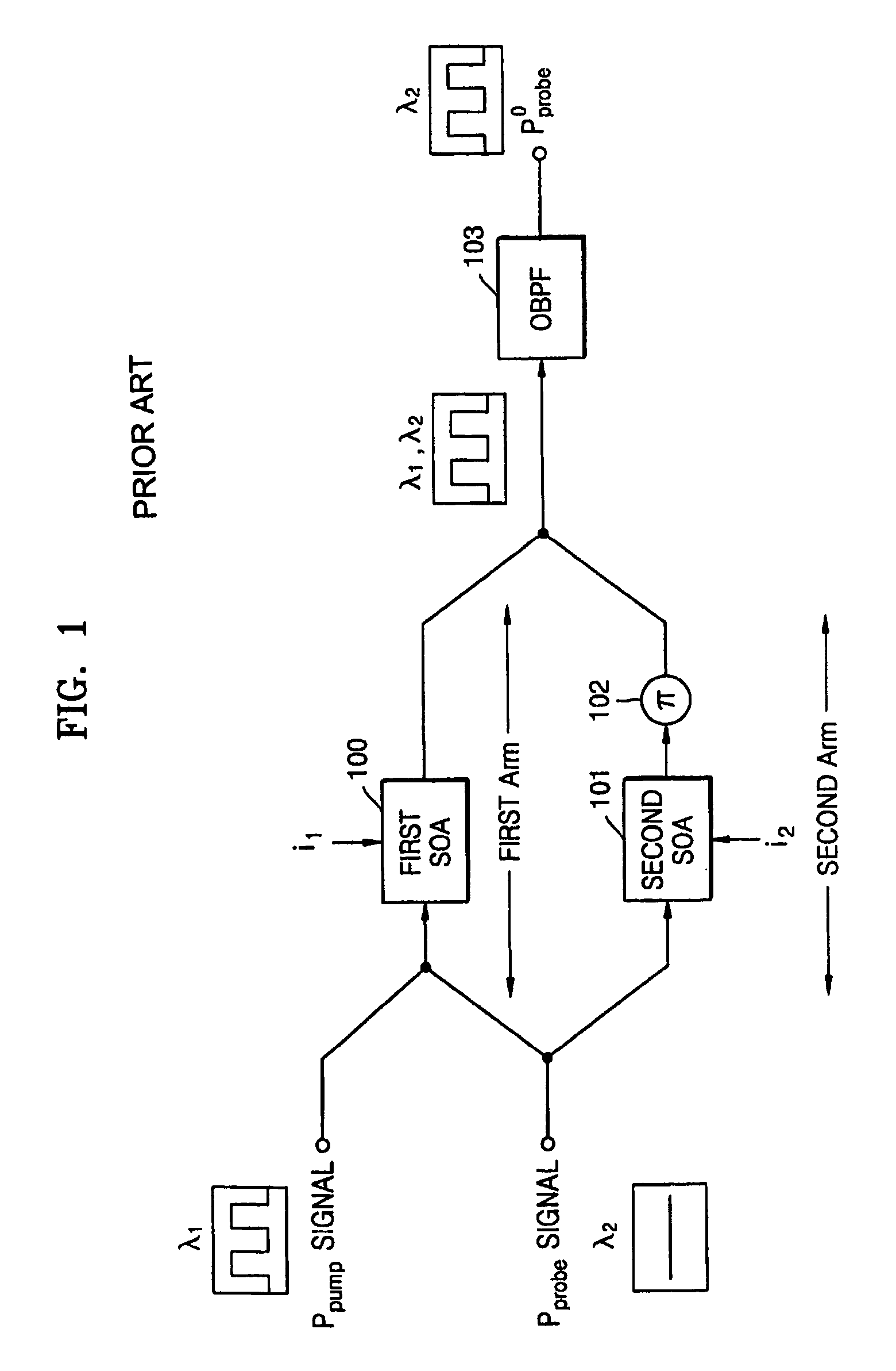
A phase optimization apparatus and method to obtain a maximum extinction ratio by feeding back a portion of an optical signal output from a Mach-Zehnder interferometer wavelength converter using XPM of a semiconductor optical amplifier to maintain an optimum phase difference between two arms. The phase optimization apparatus includes a first arm having a first semiconductor optical amplifier that amplifies a pump signal and a probe signal, a second arm having a second semiconductor optical amplifier that amplifies the probe signal, and a π phase shifter that controls the phase of the amplified signal, an optical band-pass filter that filters optical signals to output only the modulated probe signal; and a phase control unit that receives feedback to output to the π phase shifter of the second arm a phase control signal, which controls a phase difference between the first and second arms.

Description

CROSS-REFERENCE TO RELATED APPLICATIONS[0001]This application claims the priority of Korean Patent Application No. 2003-62174, filed on Sep. 5, 2003, in the Korean Intellectual Property Office, the disclosure of which is incorporated herein in its entirety by reference.BACKGROUND OF THE INVENTION[0002]1. Field of the Invention[0003]The present invention relates to an apparatus and method for operating a wavelength converter. More particularly, the invention relates to an apparatus and method to obtain a maximum extinction ratio by feeding back a portion of an optical signal output from a Mach-Zehnder interferometer wavelength converter using cross phase modulation (XPM) of a semiconductor optical amplifier to maintain an optimum phase difference between both arms.[0004]2. Description of the Related Art[0005]In order to increase a capacity and transmission speed of a communication network, efficiently operate the communication network, and improve the reliability of the network, comm...

Claims


Application Information

Patent Timeline
Patent Type & Authority Patents(United States)
IPC IPC(8): G02F1/035G02F1/35G02F1/365G02B6/12H04Q3/52G02F1/01G02F1/21G02F1/225G02F2/00H04B10/155
CPCG02F1/0123G02F1/225G02F2/004H04B10/508G02B2006/12142G02F2001/212G02F2002/006G02F1/212G02F2/006H04Q3/52
Inventor KIM, JOO-YOUPHAN, SANG-KOOK
Owner SAMSUNG ELECTRONICS CO LTD
Learn More