
Method and apparatus for resource allocation in a raid system

a raid system and resource allocation technology, applied in data conversion, program control, multi-programming arrangements, etc., can solve the problems of data loss, data loss, and failure of disks or other storage media low cost, and achieve high scalability without performance loss

Active Publication Date: 2007-08-07
NETWORK APPLIANCE INC
View PDF85 Cites 47 Cited by
  • Summary
  • Abstract
  • Description
  • Claims
  • Application Information

AI Technical Summary

Benefits of technology

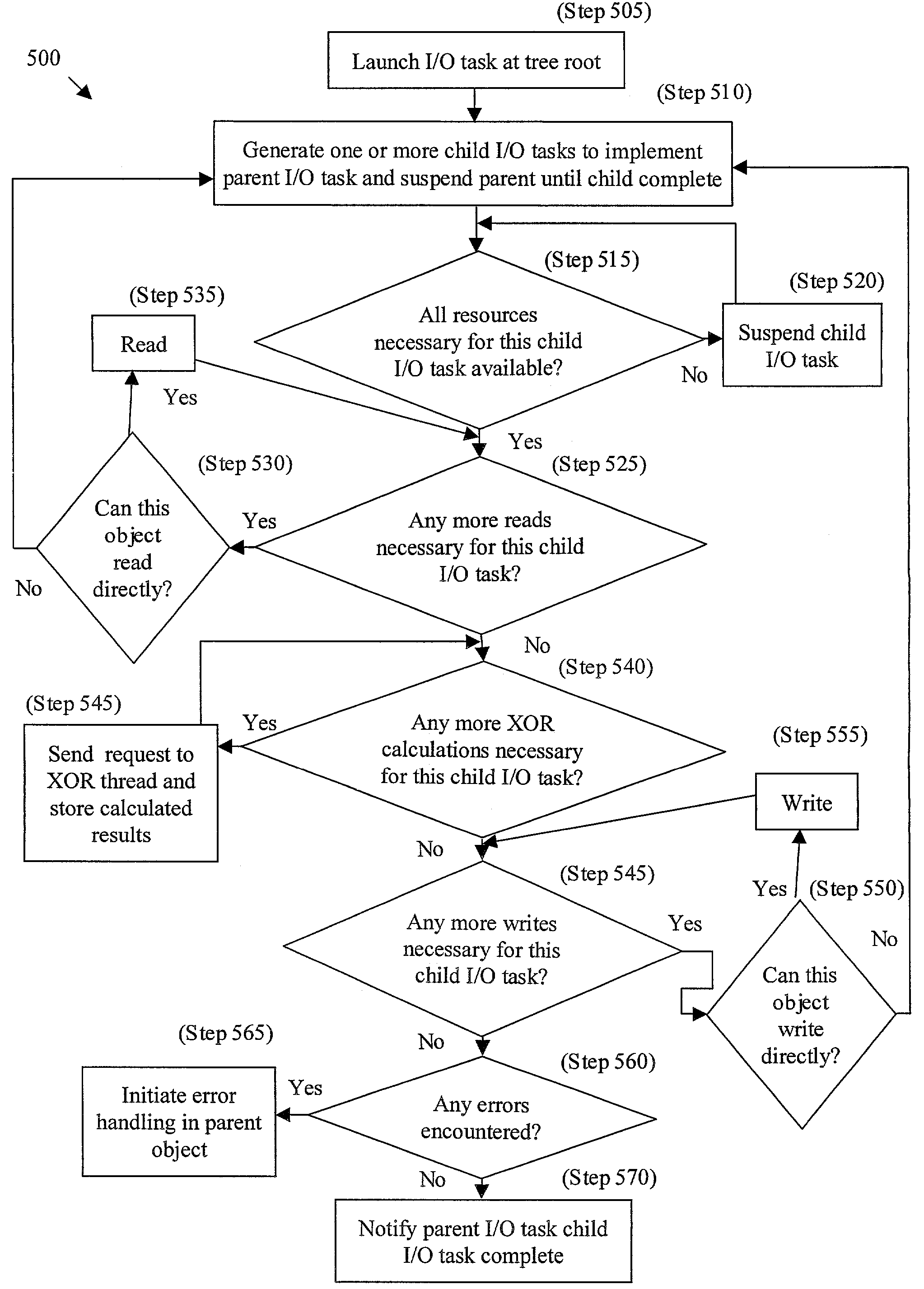
[0014]The present invention implements an I / O task architecture in which a data access request requested by the file system, for example a stripe write, is decomposed into a number of lower-level asynchronous I / O tasks that can be scheduled independently. Resources needed by these lower-level I / O tasks are dynamically assigned, on an as-needed basis, to balance the load and use resources efficiently, achieving high scalability without the loss of performance. A hierarchical order is assigned to the I / O tasks to ensure that there is a forward progression of the higher-level I / O task and to ensure that resources do not become deadlocked. This architecture allows data blocks on the same disk to be processed efficiently, for example so that a disk write involves an optimal chain length.

Problems solved by technology

In the operation of a disk array, it is fairly common that a disk, or other storage medium, such as tape, will fail.
Data can be lost when one or more storage devices fail, making it impossible to recover data from the device.
The limited number of threads used for stripe I / O and XOR operations can lead to bottlenecks, particularly during reconstruction, affecting system response time.
This can result in buffers that refer to unusable disks, which can lead to errors, from which the system may not be able to recover.
This, combined with the fact that the I / O path may handle state transitions, can lead to deadlock situations.
Such an allocation, typically accounting for worst-case error handling, results in a large allocation of resources that are never used, but nevertheless allocated and not available to other I / O threads in the system.
This can reduce the systems ability to adapt to load and configuration changes.

Method used


Image

  • Method and apparatus for resource allocation in a raid system
  • Method and apparatus for resource allocation in a raid system
  • Method and apparatus for resource allocation in a raid system

Examples


Embodiment Construction

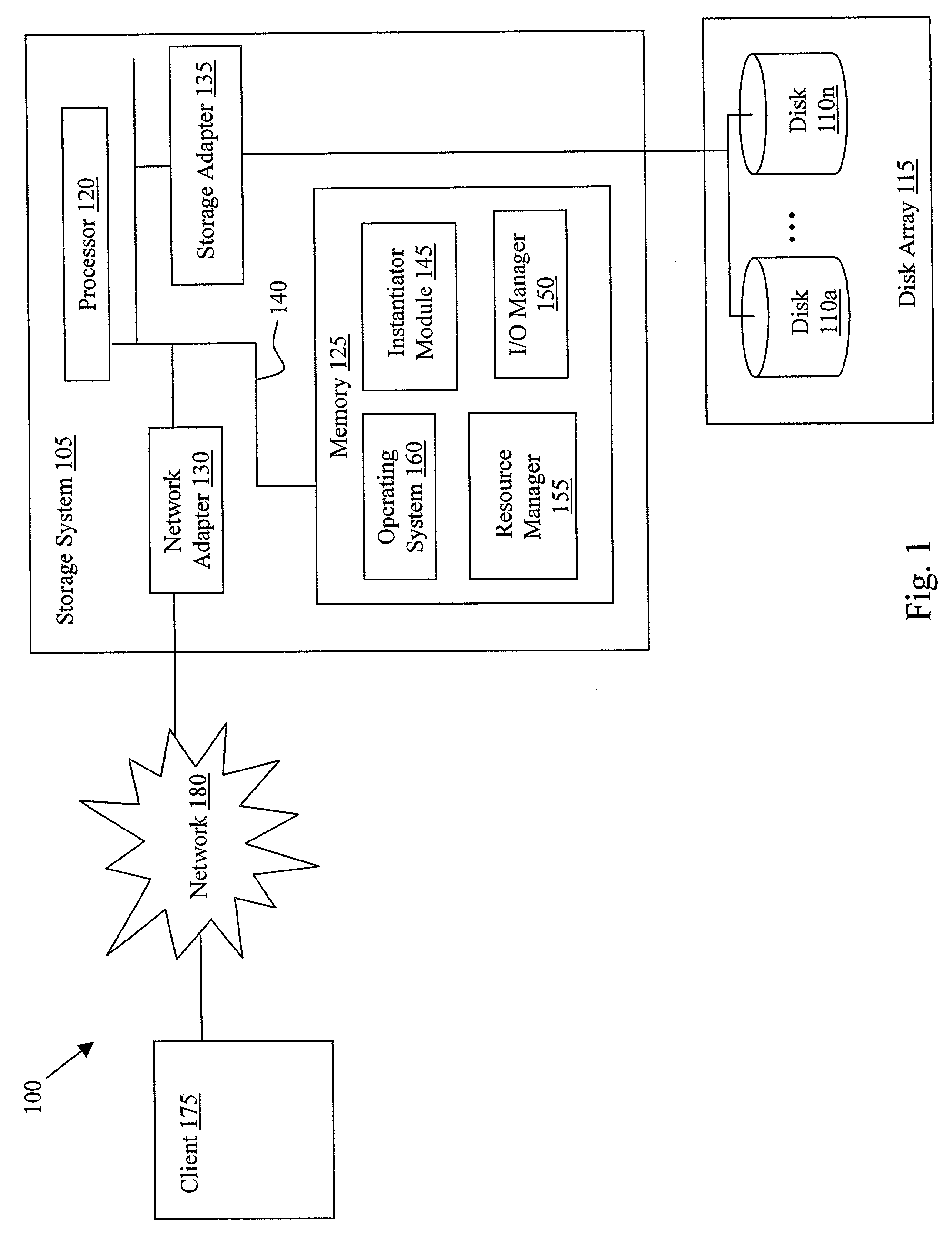
[0031]In broad overview, FIG. 1 illustrates an environment 100 including a storage system 105 that may be advantageously used with the present invention. The storage system 105 is a computer that provides storage services relating to the organization of information on storage devices, such as disks 110a, 110n, generally 110, of a disk array 115. The storage system 105 comprises a processor 120, a memory 125, a network adapter 130 and a storage adapter 135 interconnected by a system bus 140.

[0032]In the illustrative embodiment, the memory 125 includes an instantiator module 145 and an I / O manager 150 that implements an I / O task architecture for processing data access requests. The instantiator module 145 is the portion of the software and / or hardware that defines the data structures of an object, for example, an I / O task and manages the generation of each instance of an I / O task. The I / O manager 150 is the portion of software and / or hardware that implements an I / O threading mechanism...


PUM


Abstract

The present invention implements an I / O task architecture in which an I / O task requested by the storage manager, for example a stripe write, is decomposed into a number of lower-level asynchronous I / O tasks that can be scheduled independently. Resources needed by these lower-level I / O tasks are dynamically assigned, on an as-needed basis, to balance the load and use resources efficiently, achieving higher scalability. A hierarchical order is assigned to the I / O tasks to ensure that there is a forward progression of the higher-level I / O task and to ensure that resources do not become deadlocked.

Description

BACKGROUND[0001]1. Field of Invention[0002]The invention generally relates to high reliability electronic data storage, and, more particularly, to an architecture for decomposing a data access request into a number of smaller tasks.[0003]2. Description of Related Art[0004]A file server is a computer that provides file service relating to the organization of information on writeable persistent storage devices, such as memories, tapes or disks of an array. The file server or filer may be embodied as a storage system including an operating system that implements a file system to logically organize the information as a hierarchical structure of directories and files on a storage devices (e.g., disks). Each “on-disk” file may be implemented as set of data structures, e.g., disk blocks, configured to store information, such as the actual data for the file. A directory, on the other hand, may be implemented as a specially formatted file in which information about other files and directorie...

Claims


Application Information

Patent Timeline
IPC IPC(8): G06F9/46G06F11/00G06F12/00G06F3/00G06F3/06
CPCG06F3/0601G06F2003/0697G06F3/0689G06F3/0631G06F3/0644G06F3/0611G06F3/0619
Inventor LEONG, JAMESSUNDARAM, RAJESHDOUCETTE, DOUGLAS P.SCHOENTHAL, SCOTTSTRANGE, STEPHEN H.VISWANATHAN, SRINIVASAN
Owner NETWORK APPLIANCE INC
Learn More