Apparatus and method for cutting a heart valve

a heart valve and apparatus technology, applied in the field of surgical procedures for heart valve replacement, can solve the problems of releasing calcium or tissue, cutting the valve in small pieces, and causing the scissors to produce imprecise cuts,

Inactive Publication Date: 2007-08-14
ROSENGART TODD K
View PDF32 Cites 38 Cited by
  • Summary
  • Abstract
  • Description
  • Claims
  • Application Information

AI Technical Summary

Benefits of technology

[0006]A feature of the present invention is to provide an apparatus for cutting and removing tissue with a precise cut in order to avoid leaving an irregular annulus.
[0007]Another feature of the present invention is to provide a rotational axle device to allow a user to make more precise cuts into tissue and to create an annulus.
[0008]A further feature of the present invention is to provide a non-mechanical cutting device that is capable of making precise cuts into tissue without a need for transmitting mechanical forces.
[0010]Also, a feature of the present invention is to provide a first collapsible plate and a second collapsible plate to obtain any loose or cut tissues in order to reduce the risk of an embolism.

Problems solved by technology

Frequently, the valve is extremely calcified and irregular in shape and thickness, thus to remove the valve in its entirety, exertion of considerable mechanical forces are required, which can cause cutting the valve in small pieces and releasing chunks of calcium or tissue.
This conventional use of scissors often produces imprecise cuts and leaves an irregular annulus in which the surgeon must then attach or suture the replacement valve.
Because of the irregular annulus left by the use of scissors and other debriding instruments, the suturing process can be quite time-consuming.
More importantly, a considerable force cannot be used to remove a calcified valve when a device is placed and is manipulated percutaneously, as in through a transvascular catheter placed through a peripheral artery, such as the femoral artery.
For example, the cut may still be imprecise and furthermore, parts of the cut tissue can inadvertently be dislodged from the capturing device.
The dislodged tissue can cause an occlusion and embolism.
More importantly, a large diameter cutting annulus could not be placed percutaneously through a small diameter peripheral artery, such as the femoral artery.
In addition, it would be difficult and risky to transmit the considerable mechanical forces needed to cut a calcified valve through a percutaneously placed mechanical cutting device.

Method used


Image

  • Apparatus and method for cutting a heart valve
  • Apparatus and method for cutting a heart valve
  • Apparatus and method for cutting a heart valve

Examples


Embodiment Construction

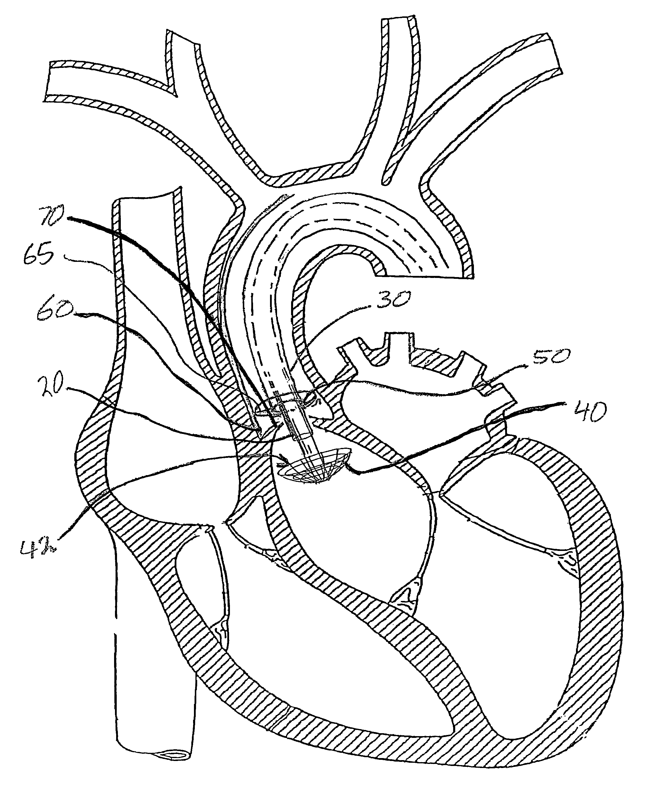
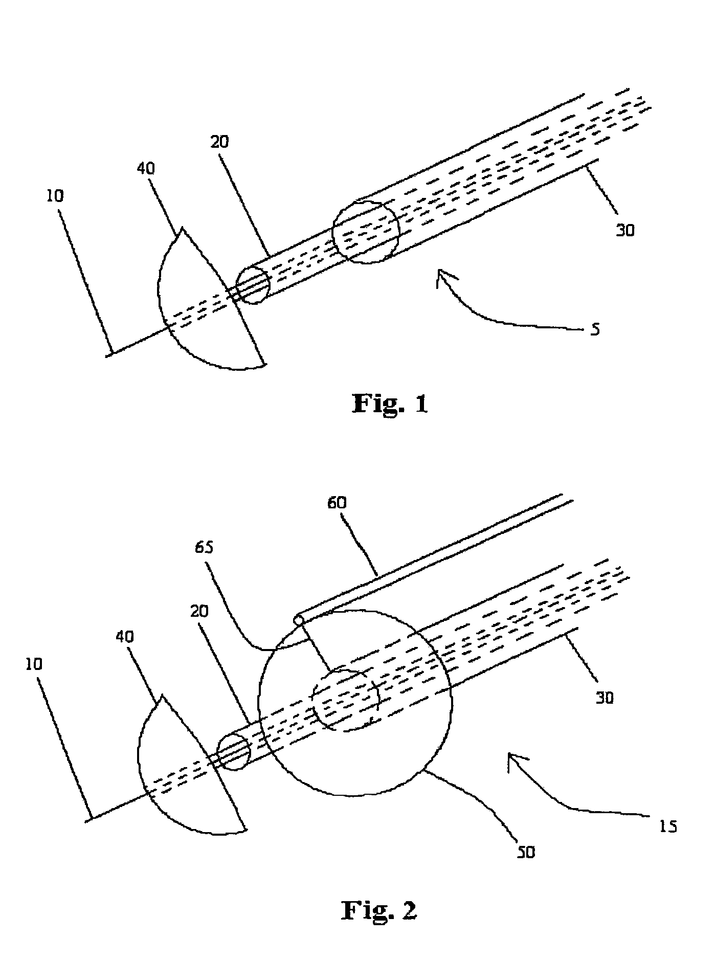
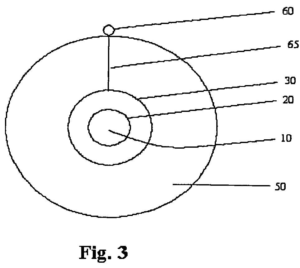
[0022]The present invention relates to an apparatus and a method for cutting and removing tissue (for example, living tissue) from a mammal. Preferably, the tissue that is being removed is a valve, and more preferably, the tissue that is being removed is a heart valve from a mammal, such as a human heart valve. In general, the apparatus of the present invention includes a rotational axle device, a first collapsible plate, and at least one non-mechanical cutting device. The present invention further relates to the method of removing a heart valve using the apparatus of the present invention.

[0023]The rotational axle device of the present invention can include any device that can be inserted into the vascular system of a patient, preferably into the aorta and / or the heart. Preferably, the rotational axle device is capable of acting as a rotational axle for devices that may be connected to or may be within an approximate distance of the rotational axle device. Preferably, the rotationa...


PUM


Abstract

An apparatus for cutting and removing a tissue is described, which includes a rotational axle device, at least one non-mechanical cutting device radially disposed from the rotational axle device, at least one device capable of protecting the heart ventricle, and a first collapsible plate. Also described is a method for cutting a tissue, such as a heart valve using the apparatus of the present invention and temporary placing a device capable of protecting the heart ventricle until a percutaneous heart valve is placed.

Description

[0001]This application claims the benefit under 35 U.S.C. §119(e) of prior U.S. Provisional Application No. 60 / 426,078 filed Nov. 13, 2002, which is incorporated in its entirety by reference herein.BACKGROUND OF THE INVENTION[0002]The surgical procedure for heart valve replacement typically involves removing a diseased heart valve and implanting an artificial heart valve device. Removal of the diseased heart valve generally involves cutting the valve from the heart to form an annulus in which the replacement valve is implanted. Conventional cutting processes for forming the heart valve annulus involve the use of scissor devices to cut the existing valve tissue from the heart. Frequently, the valve is extremely calcified and irregular in shape and thickness, thus to remove the valve in its entirety, exertion of considerable mechanical forces are required, which can cause cutting the valve in small pieces and releasing chunks of calcium or tissue.[0003]This conventional use of scissor...

Claims


Application Information

Patent Timeline
Patent Type & Authority Patents(United States)
IPC IPC(8): A61B17/32A61B17/00A61B17/22A61B18/14A61B18/22A61B18/24A61B19/00
CPCA61B17/320725A61B18/24A61B18/1492A61B2017/00243A61B2017/22051A61B2017/22078A61B2017/22097A61B2018/00214A61B2018/00898A61B2018/2238A61B2019/409A61B2090/049
Inventor ROSENGART, TODD K.
Owner ROSENGART TODD K
Why Eureka
Try Eureka