
Nitrogen sources for molecular beam epitaxy

a technology of molecular beam and nitrogen source, which is applied in the direction of chemically reactive gas, crystal growth process, polycrystalline material growth, etc., can solve the problem of large oversupply of hydrogen

Inactive Publication Date: 2007-08-14
II VI DELAWARE INC
View PDF11 Cites 21 Cited by
  • Summary
  • Abstract
  • Description
  • Claims
  • Application Information

AI Technical Summary

Benefits of technology

[0015]The principles of the present invention provide for new MBE nitrogen sources and their applications. By using nitrogen sources according to the principles of the present invention, nitrogen-containing thin films can be successfully deposited using MBE. Accordingly, the principles of the present invention further provide for a method of growing nitrogen-containing materials on a crystalline substrate using MBE. Such a method includes locating a crystalline substrate i...

Problems solved by technology

Beneficially, the NHx radicals are formed such that a large oversupply of hydrogen results.

Method used


Image

  • Nitrogen sources for molecular beam epitaxy
  • Nitrogen sources for molecular beam epitaxy
  • Nitrogen sources for molecular beam epitaxy

Examples


Embodiment Construction

[0024]Reference will now be made in detail to embodiments of the present invention. Such embodiments are suitable for fabricating nitrogen-containing layers, such as those used in VCSELs, on a crystalline substrate using MBE.

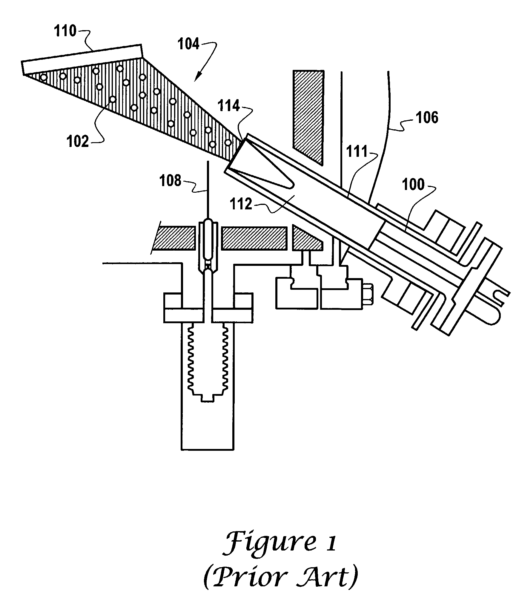
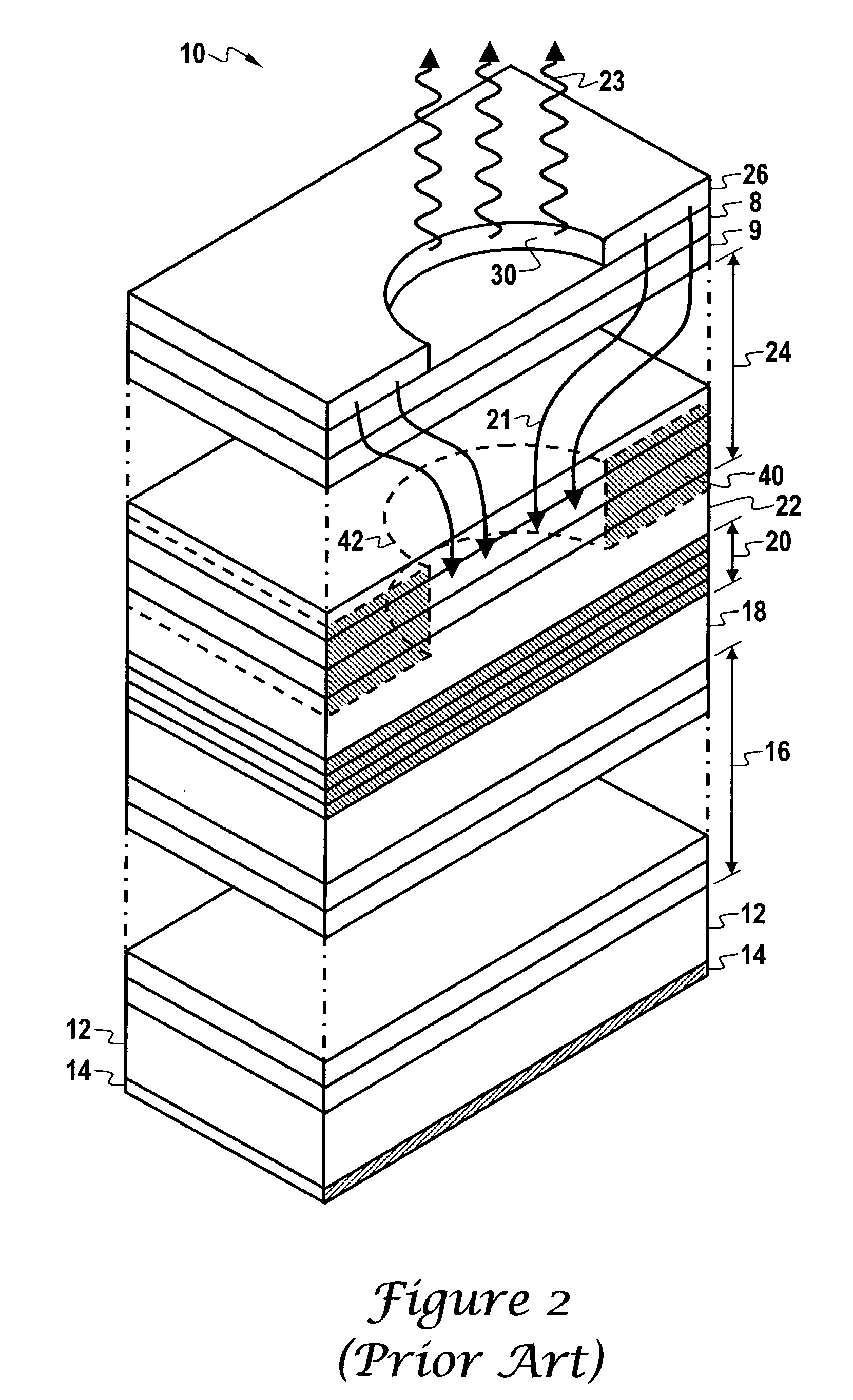
[0025]As previously described, FIG. 1 illustrates an MBE apparatus. Referring once again to FIG. 1, the crystalline substrate 110 is now considered to be a partially fabricated VCSEL, reference FIG. 2, onto which a nitrogen-containing layer is to be formed.

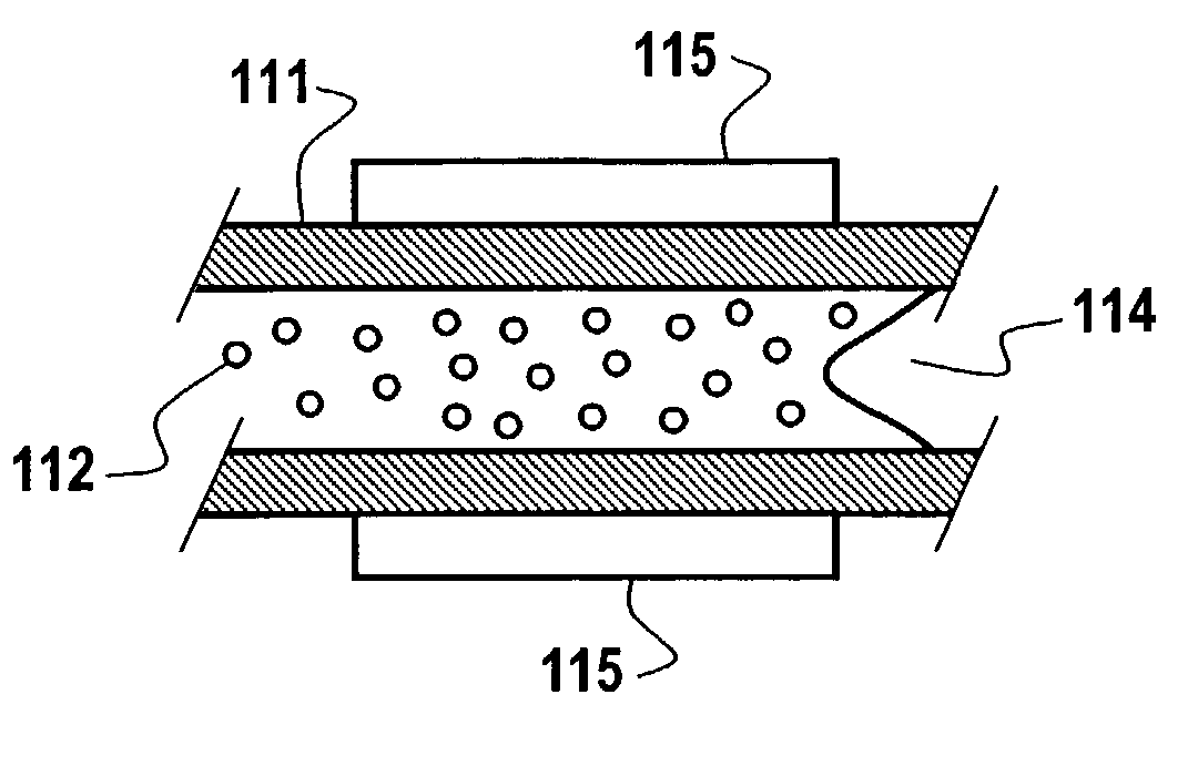
[0026]Turning now to FIG. 3, the effusion cell's 100 crucible 111 contains an effusion material 112 that is in accord with the principles of the present invention. In particular, the effusion material 112 is dimethylhydrazine, tertiarybutylhydrazine, nitrogentrifluoride, or NHx radicals.

[0027]With dimethylhydrazine, tertiarybutylhydrazine, nitrogentrifluoride, or NHx radicals in the effusion cell 100 of FIG. 1, the heater 115 heats the contained material to the proper temperature. Turning back to FIG. 1, the c...


PUM


Abstract

MBE nitrogen sources of dimethylhydrazine, tertiarybutlyhydrazine, nitrogentrifloride, and NHx radicals. Those nitrogen sources are beneficial in forming nitrogen-containing materials on crystalline subtrates using MBE. Semiconductor lasers in general, and VCSEL in particular, that have nitrogen-containing layers can be formed using such nitrogen sources.

Description

CROSS-REFERENCE TO RELATED APPLICATIONS[0001]Not applicable.BACKGROUND OF THE INVENTION[0002]1. Field of the Invention[0003]The present invention generally relates to the field of molecular beam epitaxy (MBE). More specifically, the present invention relates to MBE nitrogen sources.[0004]2. Discussion of the Related Art[0005]Molecular beam epitaxy (MBE) is a well-established method of forming thin film depositions on crystalline substrates. The MBE process is performed by heating a crystalline substrate in a vacuum so as to energize the substrate's lattice structure. Then, an atomic or molecular mass beam(s) is directed onto the substrate's surface. When the directed atoms or molecules arrive at the substrate's surface the directed atoms or molecules encounter the substrate's energized lattice structure. The energetic lattice structure then accepts oncoming atoms, possibly after those atoms are separated and removed from molecule. Over time, the oncoming atoms form a film that is ch...

Claims


Application Information

Patent Timeline
IPC IPC(8): C30B25/12C30B25/14C30B23/02H01L21/205
CPCC30B23/02C30B29/40H01L21/0254H01L21/0262H01L21/02631
Inventor JOHNSON, RALPH H.KIM, JIN K.GUENTER, JAMES K.
Owner II VI DELAWARE INC
Learn More