
Multiple signal intermodulation reduction system

a multi-signal and intermodulation technology, applied in the field of antenna communication systems, can solve the problems of reducing system communication, compromising the security of the main transmit channel, and containing large undesirable intermodulation products in the output signals of amplifiers, and achieve the effect of reducing intermodulation products

Active Publication Date: 2007-08-14
THE AEROSPACE CORPORATION
View PDF5 Cites 18 Cited by
  • Summary
  • Abstract
  • Description
  • Claims
  • Application Information

AI Technical Summary

Benefits of technology

The invention is a system that reduces intermodulation products of two amplified signals. It uses fixed phase shifters to combine two input signals and produce a composite output signal with significantly reduced levels of intermodulation products. The system can be used in a transmitter, receiver, or combined in a transceiver. The technical effect of the invention is to improve the quality of signals transmitted or received through a network.

Problems solved by technology

Unfortunately, mixing of the signal components within the amplifier when operated in saturation would cause the amplifier output signals to contain large undesirable intermodulation products.
These intermodulation products would then produce spurious transmitting beams that could compromise the security of the main transmit channels.
The intermodulation distortion in phased-array amplifiers degrades system communications.
Intermodulation products can interfere with other desired transmitted signals.
Intermodulation products can interfere with other users.
And, intermodulation products may contribute to interception by unwanted listeners.
The transmission of these intermodulation products is likely to exceed constraints on spurious emission levels.
Thus, the phased array is usually limited to transmitting a single signal at a time.
The feed forward technique, however, may produce a severe reduction in efficiency.
If the traditional single-amplifier linearization techniques were applied to the phased array, a large number of linearization circuits would be required.
The negative impact on system efficiency, weight, power, and size would render the system impractical.
This method does not however cancel intermodulation tones generated by the presence of two signals introduced at the amplifier input port.

Method used


Image

  • Multiple signal intermodulation reduction system
  • Multiple signal intermodulation reduction system
  • Multiple signal intermodulation reduction system

Examples


Embodiment Construction

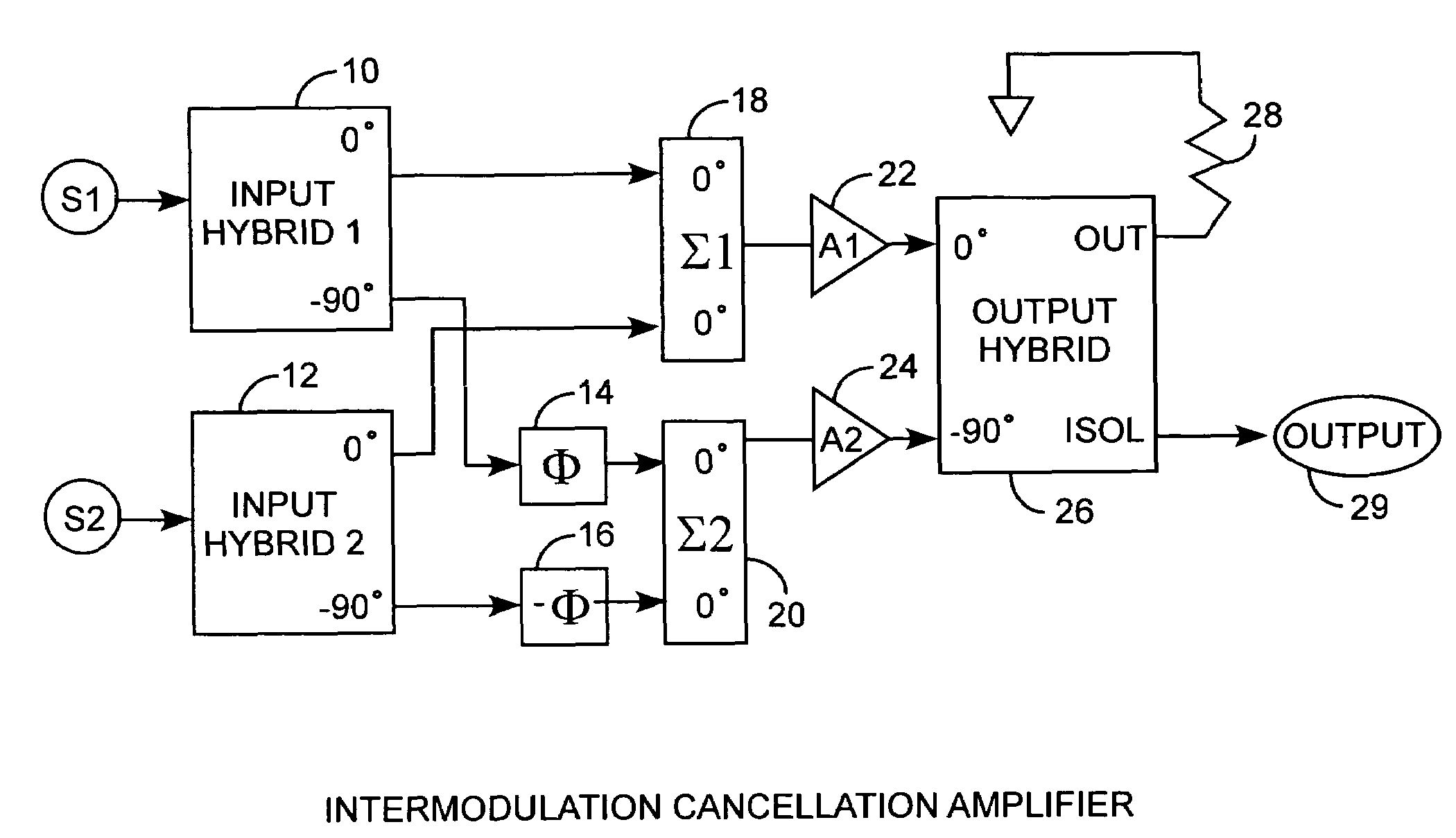
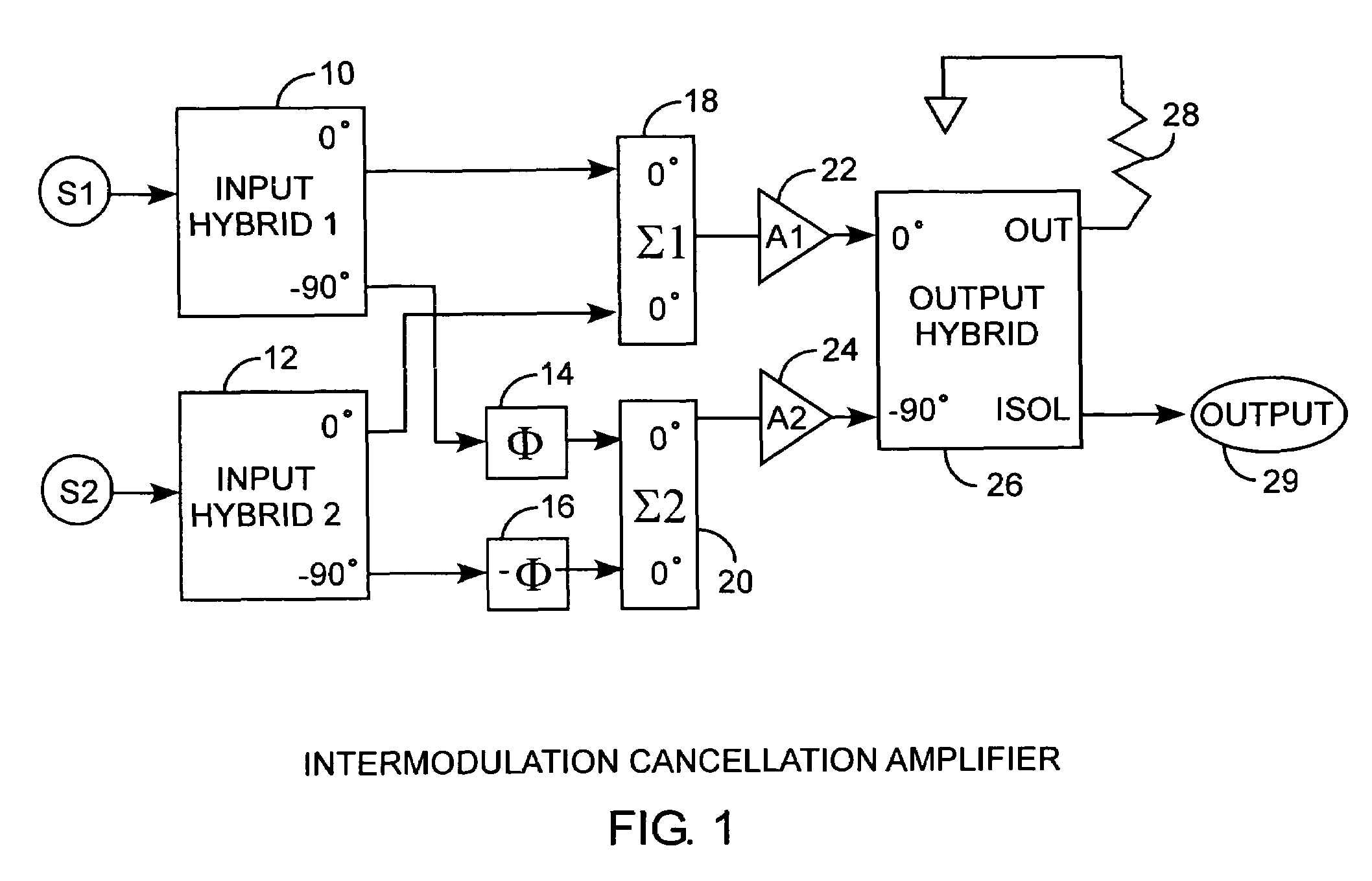
[0020]An embodiment of the invention is described with reference to the figures using reference designations as shown in the figures. Referring to FIG. 1, a balanced amplifier topology is shown for amplifying two input signals S1 and S2 into respective first and second hybrids 10 and 12. Each of the quadrature hybrids 10 and 12 have a 0° inphase output and 90° quadrature output. The 90° quadrature outputs from hybrids 10 and 12 are respectively routed to a Φ first fixed phase shifter 14 and −Φ second fixed phase shifter 16. The 0° inphase outputs are not phase shifted but summed by a first summer 18 for providing a summed inphase output, that in turn, is amplified by a first amplifier 22 for providing an amplified inphase output. The Φ and −Φ phased shifted quadrature signals are summed by a second summer 20 for providing a summed quadrature output, that in turn, is amplified by a second amplifier 24 for providing an amplified quadrature output. The amplified inphase and quadrature ...


PUM


Abstract

An intermodulation product reduction or cancellation amplifier received two input signals that are split in quadrature wherein the inphase outputs are summed and then amplified as an inphase signal, and the quadrature outputs are fixed-phase phase-shifted, then summed and then amplified as a quadrature signal. The inphase and quadrature signals are fed into an output hybrid for canceling intermodulation products, where the fixed-phase phase shift is + / −60° for reducing 3rd order, + / −36° for reducing 5th order, and + / −25.71° for reducing 7th order intermodulation products, for examples, for improved signal communications of the two signals over a common antenna or link.

Description

STATEMENT OF GOVERNMENT INTEREST[0001]The invention was made with Government support under contract No. F04701-00-C-0009 by the Department of the Air Force. The Government has certain rights in the invention.FIELD OF THE INVENTION[0002]The invention relates to the field of antenna communication systems. More particularly, the present invention relates to intermodulation reduction when transmitting or receiving two signals in communication systems.BACKGROUND OF THE INVENTION[0003]Space-based phased arrays composed of hundreds of elements can be used for microwave communications systems. The phased-array design allows for rapid placement of the beam and rapid adjustment of beam characteristics to avoid jamming. Also, phased arrays degrade gracefully and demonstrate general, flexibility unlike a dish antenna with a fixed beam. Efficiency of the phased array is one important design consideration. Phased arrays usually transmit one signal at any one time. In order to operate in the most ...

Claims


Application Information

Patent Timeline
Patent Type & Authority Patents(United States)
IPC IPC(8): H03F3/68H04L25/49
CPCH03F1/26H03F1/3223H03F3/602H03F2200/204H03F2200/372
Inventor KSIENSKI, DAVID A.MACGOWAN, KEVEN S.OSOFSKY, SAMUEL S.YOUNG, ALBERT M.TAM, THOMAS T.
Owner THE AEROSPACE CORPORATION
Learn More