Microactuated dimple for head suspensions

a dimple and microactuation technology, applied in the direction of head support, record information storage, instruments, etc., can solve the problems of reaction force excitation of undesired off-track displacement modes, the loss of a large amount of slider displacement, and the difficulty of motor and servo control system to quickly and accurately position the read/write head

Inactive Publication Date: 2007-08-14
HUTCHINSON TECH
View PDF25 Cites 74 Cited by
  • Summary
  • Abstract
  • Description
  • Claims
  • Application Information

AI Technical Summary

Benefits of technology

[0011]A head suspension is provided for supporting a head slider over a disk in a dynamic storage device and providing precise movement of the head slider relative to tracks on the disk. The head suspension includes a load beam, a flexure having a slider bonding region, and a dimple interface transmitting a load beam force to the slider bonding region. The head suspension further includes a microactuator mounted to the load beam. Movement of the microactuator is transmitted through the dimple interface by action of frictional forces at the dimple interface so as to cause movement of the head slider

Problems solved by technology

As track density increases, however, it becomes increasingly difficult for the motor and servo control system to quickly and accurately position the read/write head over the desired track.
One problem with this type of set up results from the need for the microactuator to produce enough force to overcome its own internal stiffness so that the desired amount of displacement is generated at the read/write head of the slider.
If the flexure is too compliant in both the in-plane and out-of-plane displacement directions, much of the slider displacement may be lost due to displacement/twisting of the flexure upon actuation.
Also, since the reaction forces are transmitted from the microactuator to the flexure and then to the load beam, the reaction forces may excite undesired off-track displacement modes in the flexure.
Another problem that is encountered with such microactuator configurations, is the difficulty in transmittal of electrical signals to the slider.
However, terminating the slider in this manner could produce several problems or risks, including sta

Method used


Image

  • Microactuated dimple for head suspensions
  • Microactuated dimple for head suspensions
  • Microactuated dimple for head suspensions

Examples


example

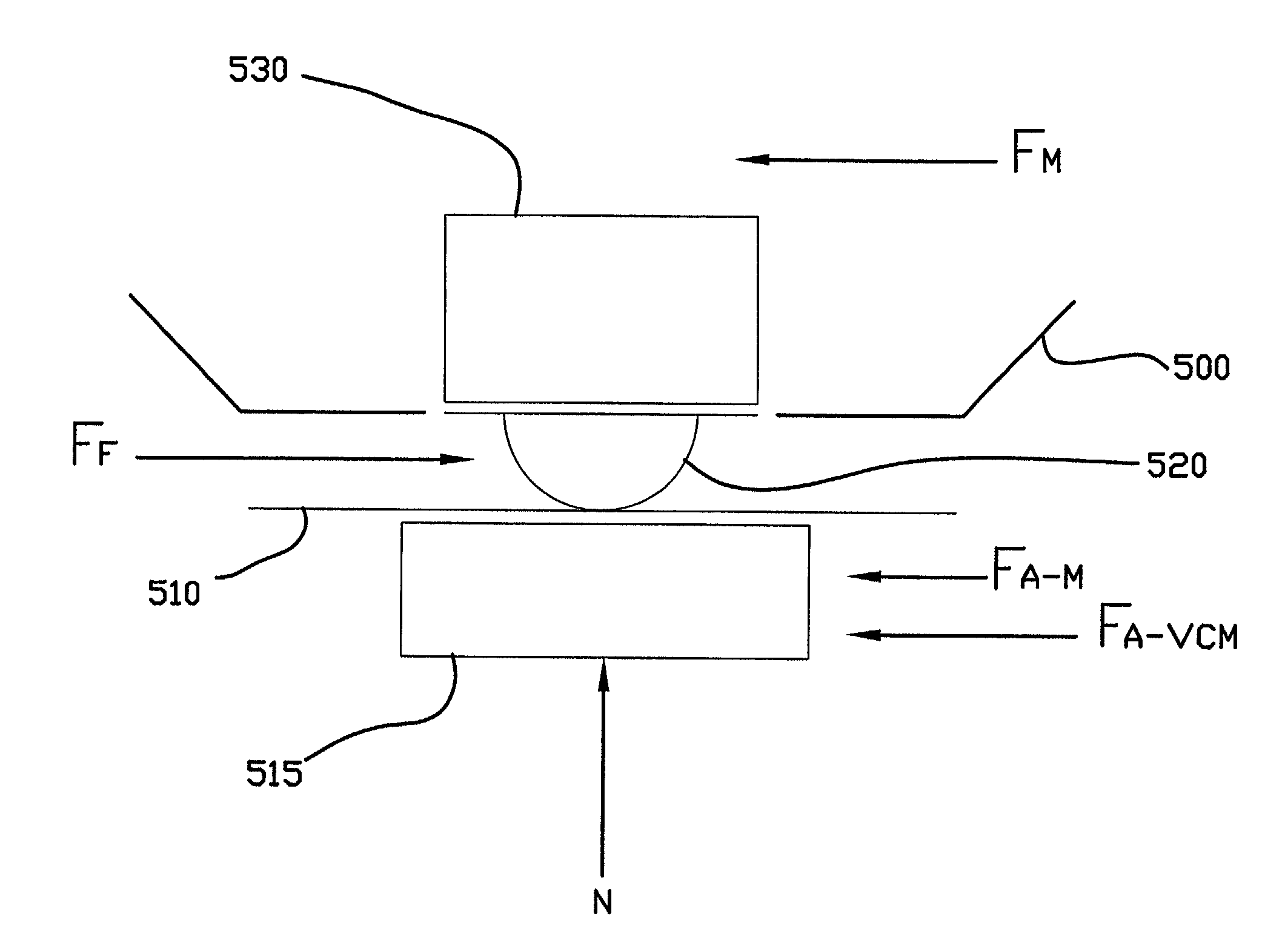
[0048]The following example illustrates that the stiction force is sufficient to resist both the static and dynamic forces acting at the dimple interface of a head slider, such as those described in the above embodiments in accordance with the present invention, under normal or standard operating conditions. Referring to FIG. 13, a free body diagram is shown illustrating a dimple interface and the corresponding forces acting upon it. In this example, a stainless steel load beam 500 is shown with a microactuator 530 mounted upon it above a dimple 520 that contacts a stainless steel flexure 510. A head slider 515 is mounted to the flexure 510 beneath the dimple 520. No modifications have been made to increase the coefficient of friction at the dimple interface.

[0049]N represents the normal force a the dimple interface, also known as the gram load. FF represents the dimple stiction force. FM represents the static force of the microactuator 530 needed to displace the slider 515 a given ...


PUM


Abstract

A head suspension for supporting a head slider over a disk in a dynamic storage device and providing precise movement of the head slider relative to tracks on the disk. The head suspension includes a load beam, a flexure having a slider mounting region, and a dimple interface transmitting a load beam force to the slider mounting region. The head suspension further includes a microactuator mounted to the load beam. Movement of the microactuator is transmitted through the dimple interface by action of frictional forces at the dimple interface so as to cause movement of the slider mounting region transverse to tracks on the disk. A method of precisely moving a head slider supported by a head suspension includes providing and driving a microactuator configured to transmit movement of the microactuator to a slider mounting region through a dimple interface by action of frictional forces at the dimple interface.

Description

[0001]This application claims priority to a U.S. provisional patent application Ser. No. 60 / 231,894, entitled MICROACTUATED DIMPLE FOR PIEZOELECTRIC AND ELECTROSTATIC MICROACTUATORS, filed on Sep. 11, 2000 now abandoned, which is wholly incorporated by reference herein.FIELD OF THE INVENTION[0002]This invention relates to head suspensions with microactuation provided to a head slider through a load beam / flexure interface or dimple.BACKGROUND OF THE INVENTION[0003]In a dynamic rigid disk storage device, a rotating disk is employed to store information. Rigid disk storage devices typically include a frame to provide attachment points and orientation for other components, and a spindle motor mounted to the frame for rotating the disk. A read / write head is formed on a “head slider” for writing and reading data to and from the disk surface. The head slider is supported and properly oriented in relationship to the disk by a head suspension that provides both the force and compliance neces...

Claims


Application Information

Patent Timeline
IPC IPC(8): G11B21/10
CPCG11B5/4826G11B5/5552
Inventor KRINKE, TODD A.
Owner HUTCHINSON TECH
Why Eureka
Try Eureka