Method and apparatus for burst scheduling

a technology of optical switching and burstswitching, applied in the field of telecommunications, can solve the problems of significant loss of statistical multiplexing efficiency, increase in capacity, and limited use of optical switching for facility management/control applications, and achieve the effect of reducing the amount of scheduling information

Inactive Publication Date: 2007-08-14
ALCATEL LUCENT SAS
View PDF5 Cites 12 Cited by
  • Summary
  • Abstract
  • Description
  • Claims
  • Application Information

AI Technical Summary

Benefits of technology

[0012]The present invention provides significant advantages over the prior art. First, it allows control packets to be scheduled efficiently and quickly. Second, the use of predetermined set of payload envelopes minimizes the amount of scheduling information that needs to be stored. Third, a synchronous payload envelope may be used to transport the information.

Problems solved by technology

However, the increased capacity creates a serious mismatch with current electronic switching technologies that are capable of switching data rates up to a few gigabits per second, as opposed to the multiple terabit per second capability of DWDM.
This could lead to a significant loss of statistical multiplexing efficiency when the parallel channels are used simply as a collection of independent links, rather than as a shared resource.
Different approaches advocating the use of optical technology in place of electronics in switching systems have been proposed; however, the limitations of optical component technology has largely limited optical switching to facility management / control applications.
Previous optical burst-switched networks designed to directly handle end-to-end user data channels have been disappointing and have shown the limitations of current optical components.
Scheduling of the BHPs has been found to be extremely challenging.

Method used


Image

  • Method and apparatus for burst scheduling
  • Method and apparatus for burst scheduling
  • Method and apparatus for burst scheduling

Examples


Embodiment Construction

[0029]The present invention is best understood in relation to FIGS. 1-14 of the drawings, like numerals being used for like elements of the various drawings.

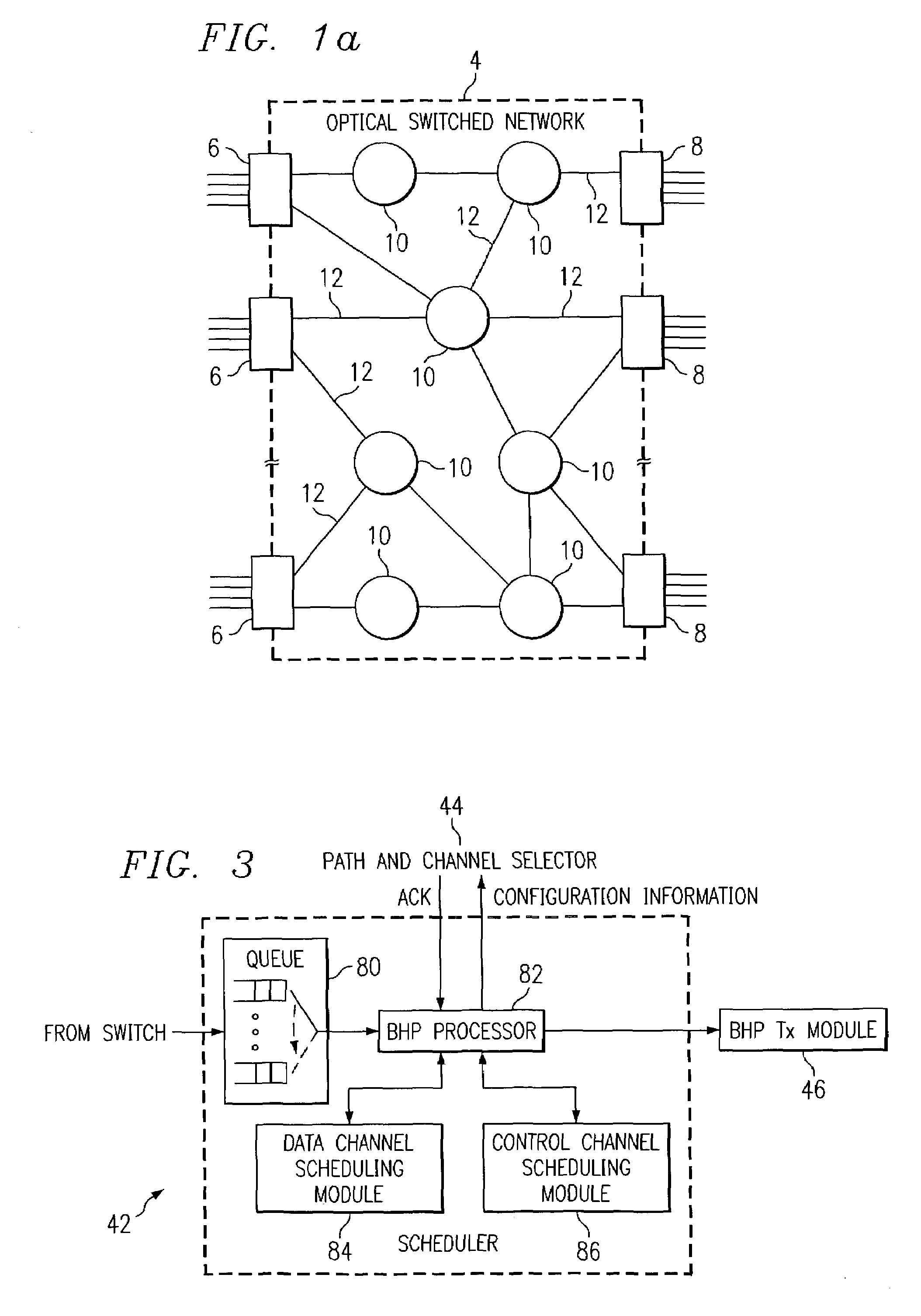
[0030]FIG. 1a illustrates a general block diagram of an optical burst switched network 4. The optical burst switched (OBS) network 4 includes multiple electronic ingress edge routers 6 and multiple egress edge routers 8. The ingress edge routers 6 and egress edge routers 8 are coupled to multiple core optical routers 10. The connections between ingress edge routers 6, egress edge routers 8 and core routers 10 are made using optical links 12. Each optical fiber can carry multiple channels of optical data.

[0031]In operation, a data burst (or simply “burst”) of optical data is the basic data block to be transferred through the network 4. Ingress edge routers 6 and egress edge routers 8 are responsible for burst assembly and disassembly functions, and serve as legacy interfaces between the optical burst switched network 4 and conven...


PUM


Abstract

Control information associated with data bursts to be switched on a burst-switched router is transmitted using payload envelopes (100) on one or more control channels (16). A control channel scheduling module (86) defines sets of contiguous payload envelopes, referred to as “frontiers” (110). A frontier contains a predetermined number of payload envelopes that could be transmitted over a maximum time difference from the time of arrival of a control packet to a latest time of departure for the control packet. After selecting a control packet, a current frontier is determined from a current time and a frontier index. Scheduling information for the current and next frontiers is stored in memory (116). The memory is searched for an available gap to accommodate the control packet (144) in one of either the current set or a next frontier based on the scheduling information.

Description

CROSS-REFERENCE TO RELATED APPLICATIONS[0001]Not ApplicableSTATEMENT OF FEDERALLY SPONSORED RESEARCH OR DEVELOPMENT[0002]Not ApplicableBACKGROUND OF THE INVENTION[0003]1. Technical Field[0004]This invention relates in general to telecommunications and, more particularly, to burst-switched optical networks.[0005]2. Description of the Related Art[0006]Data traffic over networks, particularly the Internet, has increased dramatically recently, and will continue as the user increase and new services requiring more bandwidth are introduced. The increase in Internet traffic requires a network with high capacity routers capable of routing data packets of variable length. One option is the use of optical networks.[0007]The emergence of dense-wavelength division multiplexing (DWDM) technology has improved the bandwidth problem by increasing the capacity of an optical fiber. However, the increased capacity creates a serious mismatch with current electronic switching technologies that are capab...

Claims


Application Information

Patent Timeline
Patent Type & Authority Patents(United States)
IPC IPC(8): H04L12/43H04Q11/00
CPCH04Q11/0005H04Q11/0066H04Q2011/002H04Q2011/0064
Inventor CANKAYA, HAKKI C
Owner ALCATEL LUCENT SAS
Why Eureka
Try Eureka