
Image processing device and method, and recording medium

Inactive Publication Date: 2007-08-14
FUJIFILM CORP
View PDF20 Cites 11 Cited by
  • Summary
  • Abstract
  • Description
  • Claims
  • Application Information

AI Technical Summary

Benefits of technology

[0011]The present invention was developed in light of the aforementioned, and an object of the present invention is to provide an image processing device, an image processing method, and a recording medium which can pre-emptively prevent a deterioration in image quality and can pre-emptively prevent processing from requiring more time than is preferable, due to defect detection-correction processing.

Problems solved by technology

Further, in cases in which foreign matter such as dust or the like adheres to the surface of the photographic film, the foreign matter is clearly visible as a defective portion.
However, with this technique, it is difficult to eliminate the defective portions from the output image (the image which is exposed and recorded on the photographic printing paper), and the defects are merely mitigated slightly (i.e., are merely made to be slightly less noticeable).
Thus, even if invisible light is used as above, it is difficult to isolate changes in the transmitted light amount which are due to the recorded image, and changes in the transmitted light amount which are due to a scratch or foreign matter.
Problems arise in that, by carrying out the above-described defect detection-correction processing, conversely, deterioration in the image quality arises, such as edge portions in the image becoming more dull and the like, and the defect correction processing requires an unsuitably long time.

Method used


Image

  • Image processing device and method, and recording medium
  • Image processing device and method, and recording medium
  • Image processing device and method, and recording medium

Examples


first embodiment

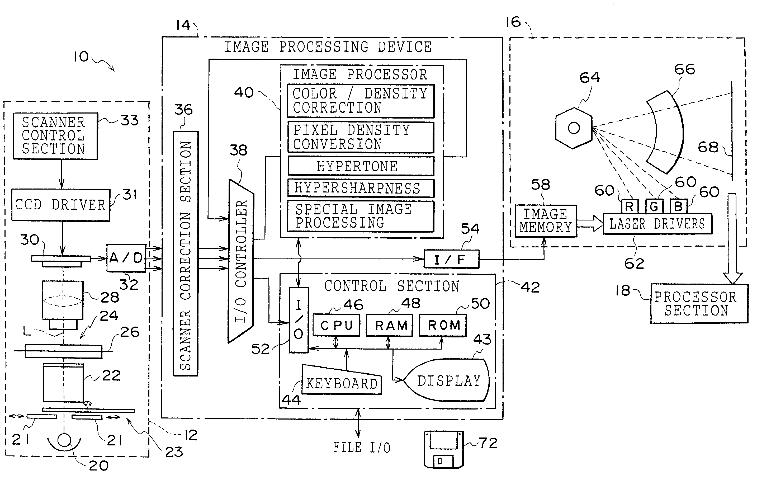
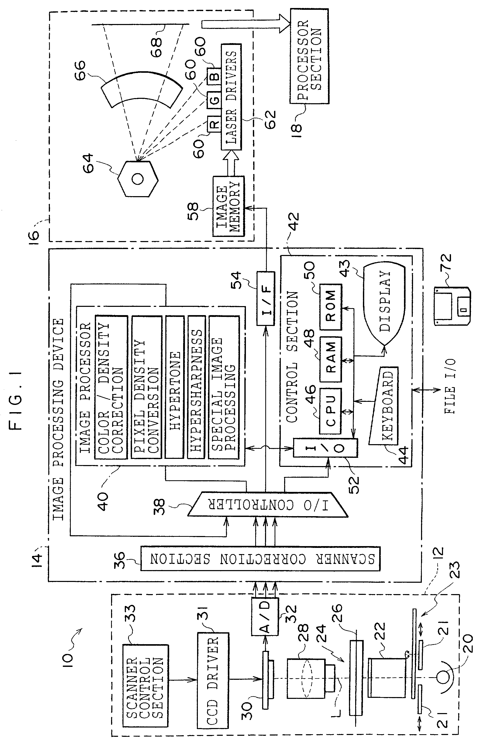
[0044]An image processing system 10 relating to the present invention is shown in FIG. 1. The image processing system 10 is formed by a film scanner 12, an image processing device 14 (e.g., a computer system) and a printer 16 connected in series. The film scanner 12 and the image processing device 14 correspond to the image processing device relating to the present invention.

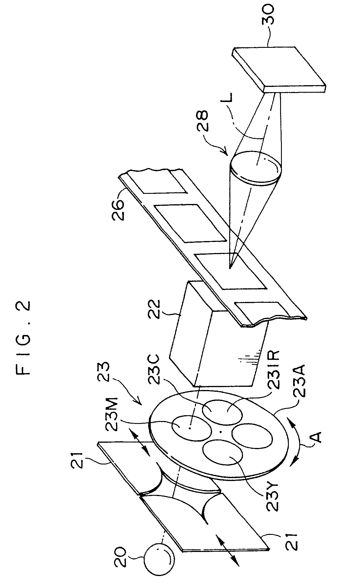
[0045]The film scanner 12 reads an image (a negative image or a positive image which is made visible by being subjected to developing processing after being used to photograph a subject) which is recorded on a photographic photosensitive material (hereinafter, simply called “photographic film”) such as a photographic film (e.g., a negative film or a reversal film) or the like. The film scanner 12 outputs image data obtained by the reading. As shown in FIG. 2 as well, the film scanner 12 is equipped with a light source 20 which is formed of a halogen lamp or the like and irradiates light onto a photographic film ...

second embodiment

[0106]Next, a second embodiment of the present invention will be described. Because the present second embodiment is structured in the same way as the first embodiment, the same portions are denoted by the same reference numerals, and description thereof is omitted. Hereinafter, explanation will be given only of the portions of the defective portion correction condition judgment process relating to the present second embodiment that differ from the defective portion correction condition judgment process described in the first embodiment.

[0107]In the defective portion correction condition judgment process relating to the first embodiment, at the time of detecting a defective portion, edge extracting processing is carried out on the IR data. However, in the defective portion correction condition judgment process of the present second embodiment, in order to use an edge, which is extracted from the image, in determining whether or not an IR image is formed, an edge is extracted from bo...


PUM


Abstract

In an image processing device which carries out processing for detecting and correcting defective portions of an image, it is possible to pre-emptively prevent the defective portion detecting and correcting processing from causing a deterioration in image quality or an excessive processing requiring time requirement. In cases in which a film type of a photographic film on which the image is recorded is a film type known to have a characteristic that an IR image is also formed at a time of image exposure and recording, and in cases in which a density distribution width of IR data is a predetermined value or more, defect detection-correction processing is cancelled. Further, in cases in which a non-image region is included in the image, either defect detection-correction is carried out only on regions other than the non-image region, or defective portion detection-correction is cancelled.

Description

BACKGROUND OF THE INVENTION[0001]1. Field of the Invention[0002]The present invention relates to an image processing device and method and a recording medium, and in particular, to an image processing device which corrects defective portions within an image as represented by image information, to an image processing method which is applicable to the image processing device, and to a recording medium on which is recorded a program for making a computer function as an image processing device.[0003]2. Description of the Related Art[0004]There are cases in which scratches are formed on an emulsion surface or back surface (the reverse surface from the emulsion surface) of a photographic film due to how the photographic film has been handled. In a case in which a scratch is formed in a place on the photographic film corresponding to an image-recorded region, when the image which is recorded on the photographic film is output (is recorded onto an image recording material such as a photogra...

Claims


Application Information

Patent Timeline
IPC IPC(8): G06K9/40H04N5/253G06T5/00G06T7/00H04N1/19H04N1/40H04N1/409
CPCG06T7/0002G06T7/0004H04N1/4097G06T5/005G06T5/50G06T2207/30144G06T2207/10008G06T2207/10024G06T2207/10048G06T5/77
Inventor YAMAGUCHI, HIROSHI
Owner FUJIFILM CORP
Learn More