System and method for providing a smart antenna

a technology of smart antennas and antennas, applied in the field of system and method for providing a smart antenna system, can solve the problems of severe delay in digital signal processing for weight calculation, and achieve the effects of improving overall coverage, reducing the cost of installation, and increasing the average data rate per user

Active Publication Date: 2007-08-14
RENDA TRUST
View PDF12 Cites 61 Cited by
  • Summary
  • Abstract
  • Description
  • Claims
  • Application Information

AI Technical Summary

Benefits of technology

[0016]The SEAM can be attached to an AP (Access point) to enhance both the transmit and receive range and coverage. Depending on the configuration the SEAM does this by a combination of beamforming and power amplification. SEAM uses a smart antenna integrated circuit to perform beamforming. For example, SEAM can employ the JSA100 Smart Antenna Integrated Circuit manufactured by Motia, Inc., Pasadena, Calif.
[0018]In the receive mode, the weights to be used with input signals from a plurality of antennas can be calculated in a blind manner to improve performance and the weighted signals combined to produce an output signal. It has been found that because of the very short acquisition time for 802.11a / g, the latency of digital signal processing for weight calculation is a severe problem which is reduced by the use of analog processing rather than digital processing. In an embodiment of the present invention, the weights are calculated with analog processing, as digital processing adds significantly more latency.
[0021]Results show a 13 dB gain with a four element smart antenna of the present invention over a single antenna system with the smart antenna on one side only, and an 18 dB gain with the smart antenna on both the client and access point. The present invention provides a “plug-and-play” adaptive array technology which can provide greater range, average data rate increases per user, and better overall coverage.
[0022]The major advantage of this system is improved performance over the standard AP without the need to use processing resources from the AP. This allows for the flexible provisioning of enhanced performance to those users who require it.
[0023]The appliqué of the present invention has the following advantages: fully 802.11 compliant; works with any transceiver chip set; virtually “plug and play;” applicable to access points and client devices; extends range up to about 4 times; increases throughput by 50% and higher; eliminates Dead Spots; reduces Power Drain up to about 90%; and has low manufacturing and operating costs. Utilizing smart antenna appliqués of the present invention to improve 802.11 systems is a cost-effective way to gain the clear benefits to WLAN performance without requiring the complete re-engineering of wireless equipment.

Problems solved by technology

It has been found that because of the very short acquisition time for 802.11a / g, the latency of digital signal processing for weight calculation is a severe problem which is reduced by the use of analog processing rather than digital processing.

Method used


Image

  • System and method for providing a smart antenna
  • System and method for providing a smart antenna
  • System and method for providing a smart antenna

Examples


Embodiment Construction

[0036]Reference will now be made in greater detail to a preferred embodiment of the invention, an example of which is illustrated in the accompanying drawings. Wherever possible, the same reference numerals will be used throughout the drawings and the description to refer to the same or like parts.

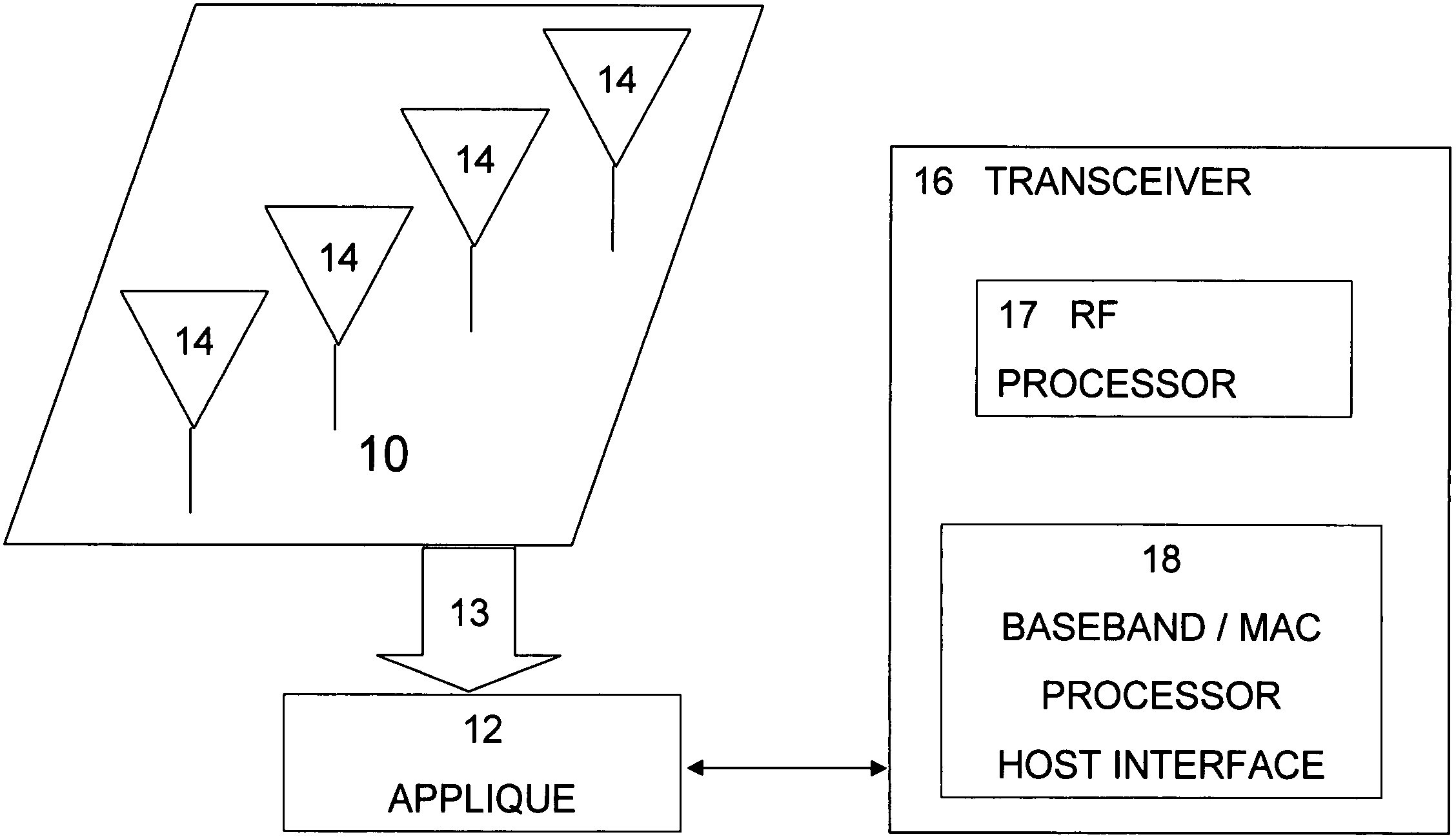
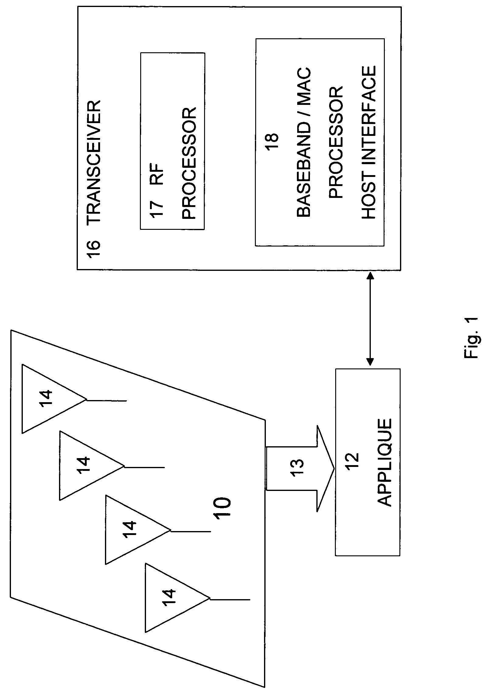
[0037]FIG. 1 is a block diagram of a system for providing a smart antenna 10 in accordance with the teaching of the present invention. Appliqué12 communicates with a plurality of antennas 14a-d and transceiver 16 using radio frequency (RF) communication techniques. Appliqué12 combines signals 13a-13d from respective antennas 14a-14d and combines them to generate input signal 17 to transceiver 16. In this embodiment, four antennas are used in system 10 and appliqué12 combines the four signals from the four antennas to generate the input signal to transceiver 16. It will be appreciated in alternative embodiments, various numbers of antennas can be used and the signals from the antennas can b...


PUM


Abstract

A smart external antenna module is proposed for wireless systems. The module allows the advantages of smart antennas to be easily added to existing wireless systems without any modification to the transceiver. Specifically, the smart antenna module weights and combines the signals received by multiple antennas to improve the received signal quality, and then when it detects that there is a signal to be transmitted by the transceiver, it turns off the receiver, turns on the transmitter and uses the receive weights to transmit the signal out of the multiple antennas to improve signal reception at the desired user. Such a module can be added to the external antenna port of an existing transceiver with no change to that transceiver.

Description

CROSS REFERENCE TO RELATED APPLICATION[0001]This application claims the benefit of U.S. Provisional Patent Application No. 60 / 526,340 filed Dec. 2, 2003 the entirety of which is hereby incorporated by reference into this application.BACKGROUND OF THE INVENTION[0002]1. Field of the Invention[0003]The present invention is directed to a system and method for providing a smart antenna system in which an antenna array can attach to an external port of a transceiver without any modification of the transceiver.[0004]2. Description of the Related Art[0005]In the past, companies had turned to wireless local area networks (WLANs) only to support low data intensive applications such as inventory management in warehouses and retail price marking in stores. For these applications, even though wireless network interface cards (NIC) are very costly, the improved efficiency derived from going wireless was worth the investment. The high price and low data rates, however, limited the usefulness and p...

Claims


Application Information

Patent Timeline
Patent Type & Authority Patents(United States)
IPC IPC(8): H04M1/00H01QH04B7/02H04B7/06H04B7/08
CPCH04B7/0615H04B7/0848
Inventor WANG, JAMES JUNE-MINGWINTERS, JACKMCCONNELL, RICHARD
Owner RENDA TRUST
Why Eureka
Try Eureka