

Select lever device for automatic transmission
- Summary
- Abstract
- Description
- Claims
- Application Information
AI Technical Summary
Benefits of technology
Problems solved by technology
Method used
Image

Examples
first embodiment
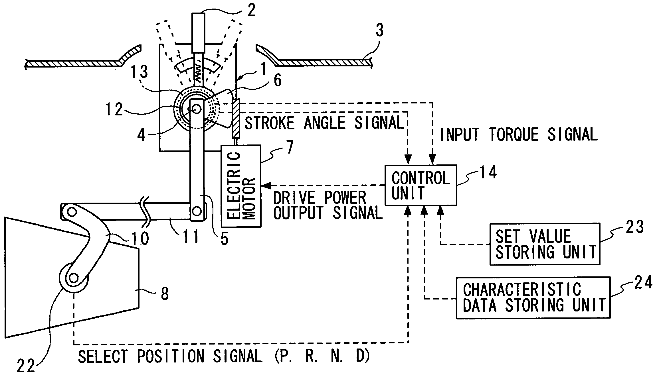
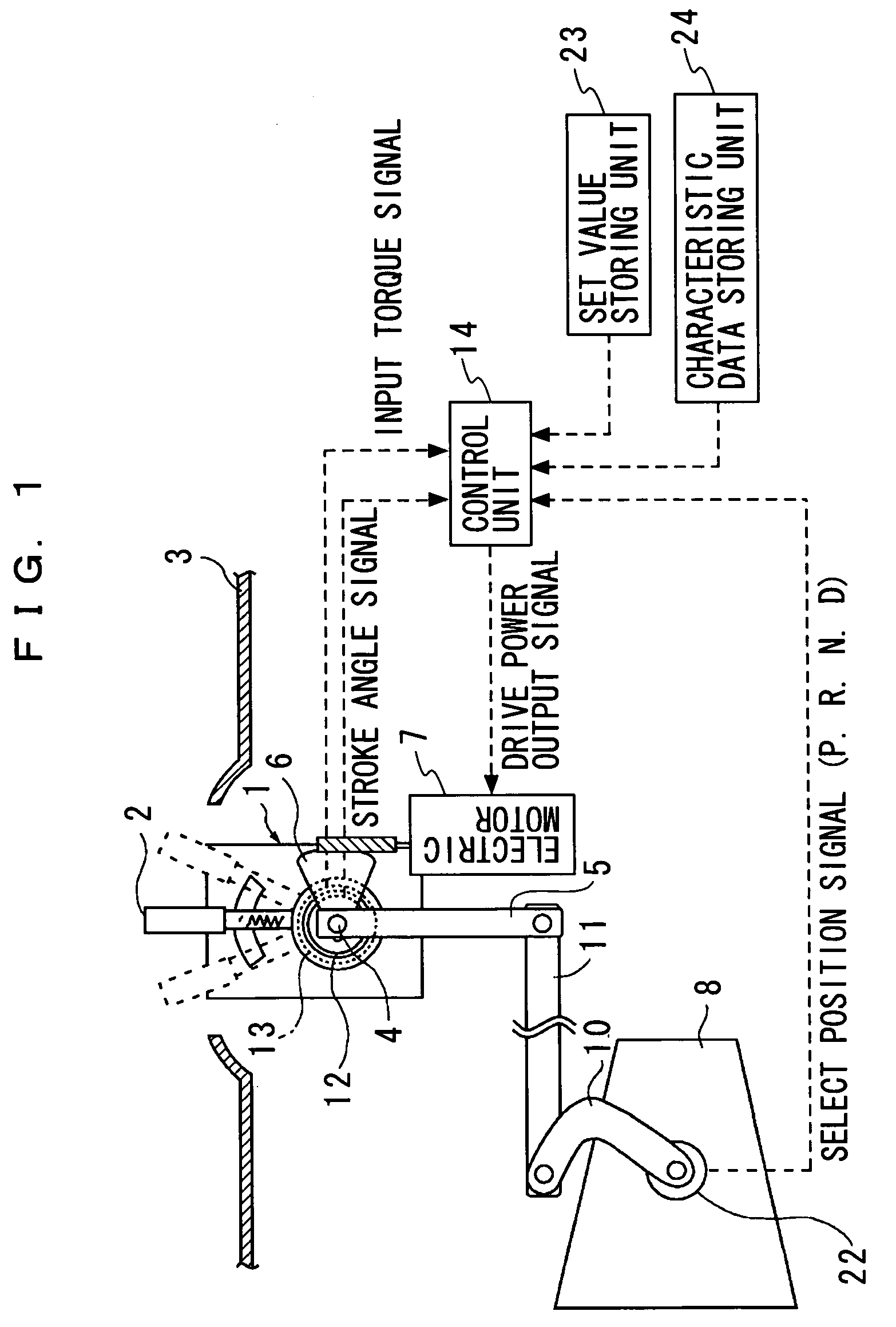
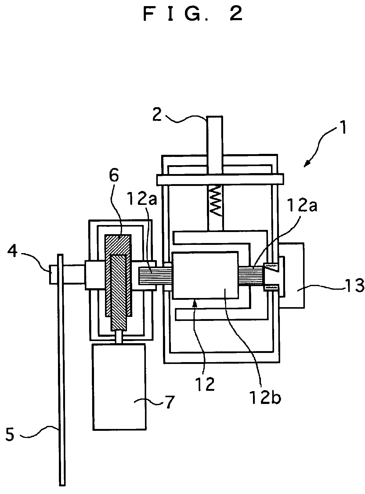
[0045]First, the construction of a select lever device for an automatic transmission according to the present invention will be described. FIG. 1 is a side view showing the construction of an automatic transmission having a select lever device of the present invention, and FIG. 2 is a fragmentary sectional rear view of the select lever device for the automatic transmission.
[0046]As shown in FIG. 1 and FIG. 2, a select lever device 1 is arranged, for example, at a center console 3 beside a driver's seat. The select lever device 1 has a select lever 2 operated by a driver and projecting above the surface of the center console 3. The select lever 2 is operated to rotate in a longitudinal direction of a vehicle at a drive shaft 4 disposed at a lower end of the select lever 2. The select lever 2, whose length is set to about 100 mm, is designed to be shorter than a conventional typical select lever by about 25 mm.
[0047]Therefore, a projecting amount of the select lever 2 into space in a ...
second embodiment
[0108]Next, a select lever device according to the present invention will be described with reference to the drawings.
[0109]In a select lever device 1 according to this embodiment, which also has the similar construction as that of the select lever device 1 according to the first embodiment shown in FIG. 1 to FIG. 3, and the correspondence relationship between the stroke angle of a select lever 2 and the output voltage of a position sensor 13 as shown in FIG. 4 is stored in a characteristic data storing unit.
[0110]In the select lever device 1 according to this embodiment, a control unit 14 computes a target assist torque that is a target value of assist torque to be outputted by an electric motor 7, based on a target assist torque map shown in FIG. 11 representing the relationship between a detected stroke angle of the select lever 2 and the preset target assist torque. Next, the target assist torque is corrected according to an actually detected input torque, and determines an outp...
third embodiment
[0144]Next, a select lever device according to the present invention will be described with reference to the drawings.
[0145]In a select lever device 1 according to this embodiment, which also has the similar construction as that of the select lever device 1 according to the first embodiment shown in FIG. 1 to FIG. 3, and the correspondence relationship between the stroke angle of a select lever 2 and the output voltage of a position sensor 13 as shown in FIG. 4 is stored in a characteristic data storing unit. The select lever device 1 according to this embodiment further includes an operating speed detecting means to detect the operating speed of the select lever 2. Further, a control unit 14 includes an overrun preventing counter that sets a target value according to the operating speed of the select lever 2 for the purpose of preventing the overrun of the select lever 2 from a desired position, and the output of the assist torque in the next select position is stopped until this t...
PUM
 Abstract
Description
Claims
Application Information