Combination apparatus for machining material with a milling cutter and a laser

a technology of laser and milling cutter, which is applied in the direction of milling equipment, multi-purpose tools, heating types, etc., can solve the problems of lasers not starting until the cutting zone is heated and the cutting zone is difficult to achiev

Active Publication Date: 2007-08-21
JENOPTIK AUTOMATISIERUNGSTECHN
View PDF20 Cites 30 Cited by
  • Summary
  • Abstract
  • Description
  • Claims
  • Application Information

AI Technical Summary

Problems solved by technology

With laser-assisted milling, the heating of the cutting zone is more difficult, since a milling cutter usually has a plurality of tips, all of which simultaneously participate in the removal of material.
The devices which are known from and described in the prior art have the disadvantage that the lasers cannot begin until after the volume to be removed by milling has been removed (two work steps), i.e., the entire machining area must be gone over twice.

Method used


Image

  • Combination apparatus for machining material with a milling cutter and a laser
  • Combination apparatus for machining material with a milling cutter and a laser
  • Combination apparatus for machining material with a milling cutter and a laser

Examples


Embodiment Construction

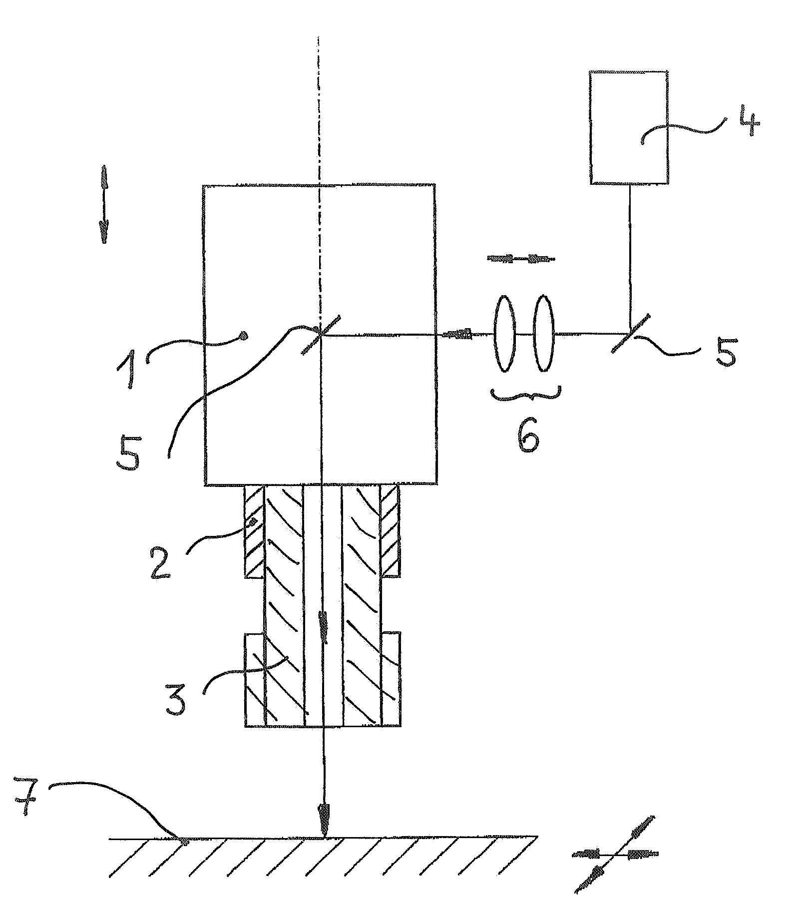
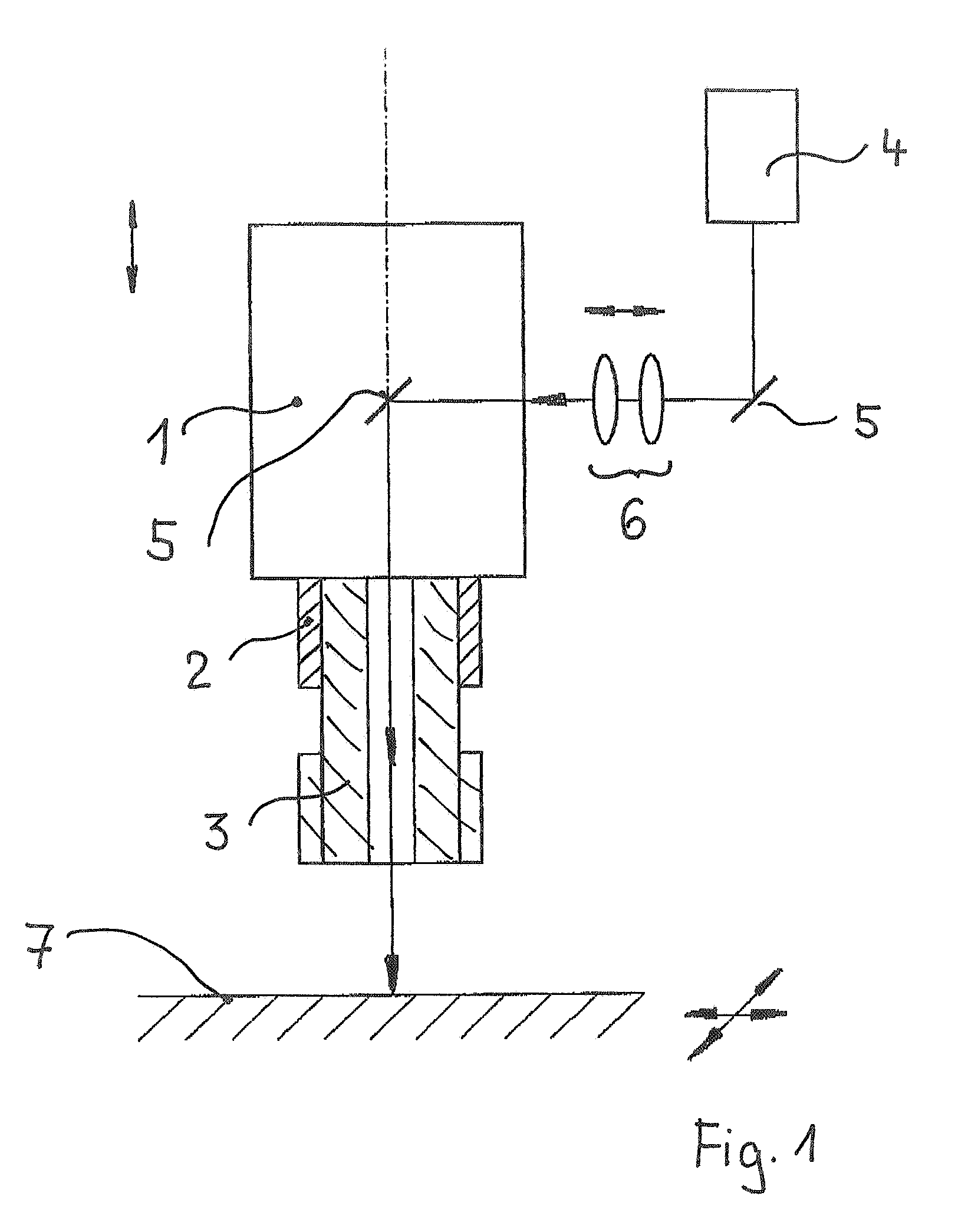
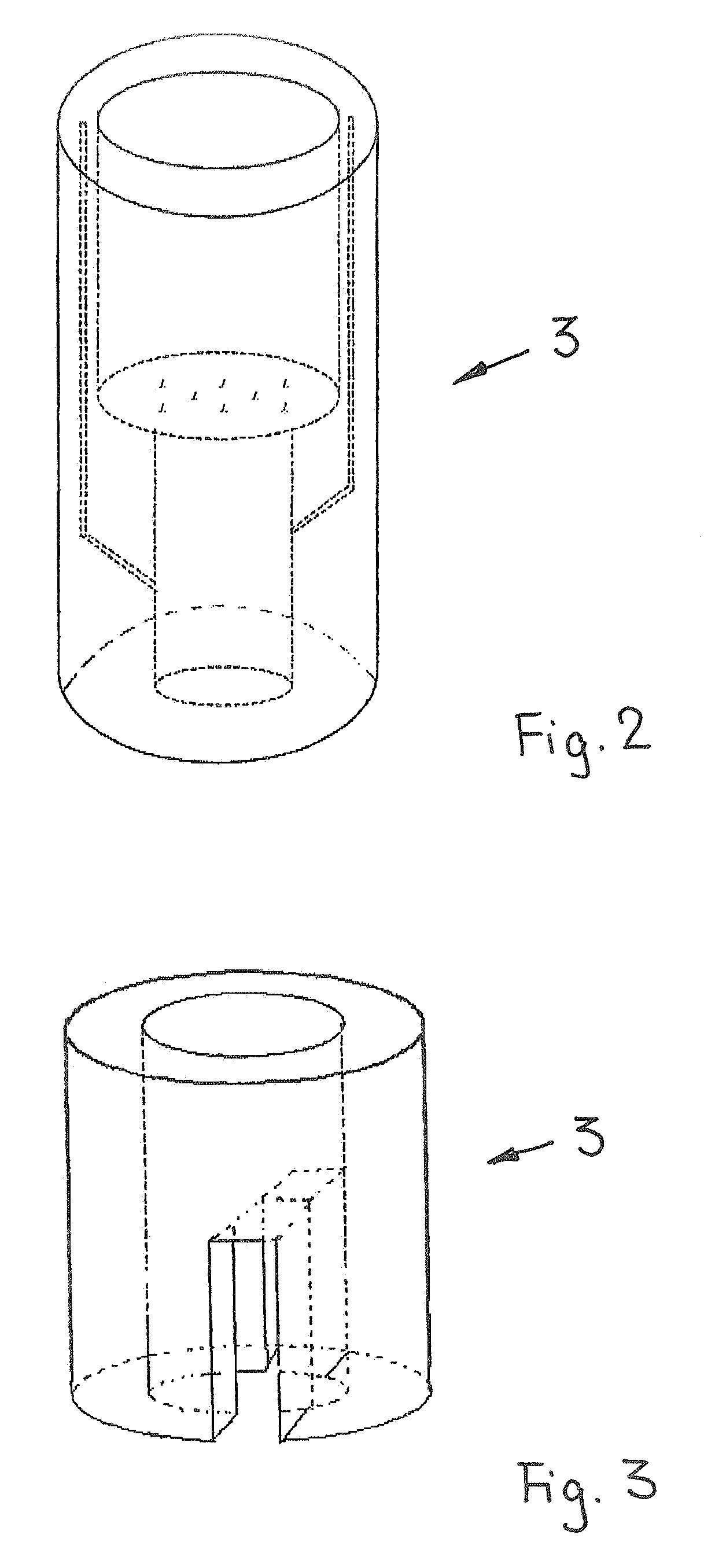
[0023]FIG. 1 shows a milling unit 1 with a motor-driven work spindle 2 for receiving a hollow milling cutter 3, in particular an end mill, a laser 4 connected to an optical transmission system, with deflecting elements 5 for coupling the laser beam into the hollow milling cutter 3, adjustable focusing optics 6, and a work table 7 for clamping the tool. Guides, driving units and controlling units for generating and controlling the relative movement of the milling unit 1 and work table 7 in three spatial dimensions and for controlling the laser 4 and adjustable focusing optics 6 are not shown. The milling cutter 3 is connected to the work spindle 2 by a standard clamping device, preferably a quick-clamping chuck. Further, units can be provided for chip extraction, for delivering and discharging cutting gas, and for cooling.

[0024]The apparatus differs from generic prior art devices in that the laser radiation is directed to the workpiece in the milling unit 1 and via the work spindle 2...


PUM

PropertyMeasurementUnit
distanceaaaaaaaaaa
timeaaaaaaaaaa
temperatureaaaaaaaaaa

Abstract

The invention is directed to an apparatus for cutting material by means of a milling cutter and laser radiation. The apparatus comprises a milling unit, a work spindle, a milling cutter, a laser, deflecting elements, focusing optics, and a work table. According to the invention, a workpiece can be milled and lasered simultaneously or successively at the same cutting location in that the laser beam is coupled into a channel coaxial to the mill axis.

Description

CROSS-REFERENCE TO RELATED APPLICATION[0001]This application claims priority of German Application No. 10 2006 003 682.4, filed Jan. 24, 2006, the complete disclosure of which is hereby incorporated by reference.BACKGROUND OF THE INVENTION[0002]a) Field of the Invention[0003]The invention is directed to an apparatus by which material can be partially removed from a workpiece by means of a milling cutter and a laser. An apparatus of this type is known generically from DE 199 10 880 A1.[0004]b) Description of the Related Art[0005]DE 41 13 633 A1 proceeds from a prior art in which workpieces which are to be worked by other machining methods in addition to laser machining are worked in different machining devices. The workpiece must be transported between machining devices and oriented to the tool in each machining device.[0006]With the aim of providing a machining device by which, besides laser machining, other machining methods can be carried out without transporting or displacing the...

Claims


Application Information

Patent Timeline
Patent Type & Authority Patents(United States)
IPC IPC(8): B23P23/00B23K26/38
CPCB23C3/28B23C5/16B23K26/0093B23P23/04B23C2220/48Y10T29/5147Y10S408/701Y10T29/5176Y10T408/34A01K1/0052F24F7/10
Inventor JANCSO, ALEX
Owner JENOPTIK AUTOMATISIERUNGSTECHN
Why Eureka
Try Eureka