Eureka AIR delivers breakthrough ideas for toughest innovation challenges, trusted by R&D personnel around the world.

Color filter substrate, color filter substrate manufacturing method, and color filter substrate manufacturing device

Inactive Publication Date: 2007-08-21
SHARP KK
View PDF5 Cites 5 Cited by
  • Summary
  • Abstract
  • Description
  • Claims
  • Application Information

AI Technical Summary

Benefits of technology

[0013]The present invention has been attained in view of the above problems, and a feature of the present invention is to provide a simple and low-cost manufacturing method for manufacturing a high-quality color filter substrate, and to provide an inexpensive and high-quality color filter substrate.
[0017]Thus, in the above method, since the coloring liquid is applied to the substrate surface with the coloring liquid in contact with the substrate surface, it is not necessary to position areas where the coloring liquid is to be applied. Further, since the coloring liquid is continuously supplied from the coloring liquid supplying section, unlike the ink jet technique, it is not necessary to control intermittent discharge of ink. This eliminates the need for a cumbersome manufacturing process and such an expensive manufacturing device as a device using the ink-jet technique.
[0019]Moreover, since the coloring liquid is applied to the substrate surface (more precisely, the lyophilic areas to be colored) while the coloring liquid is continuously brought into contact with the substrate surface, that is, the coloring liquid is directly applied to the substrate surface, the possibility that color unevenness and uncolored dots might occur in the colored layer is reduced, as compared to the ink jet technique of coloring like pointillism (application of a coloring liquid).

Problems solved by technology

However, these methods need to repeat cleaning step, applying step, exposing step, developing step for each color, resulting in difficulty in simplification of the manufacturing process.
Moreover, in the applying step, there is the problem of increase in material loss due to spin coating method.
However, there are the problems that pattern shapes capable of being formed by the electrodeposition method are limited, and a fine pitch pattern is difficult to be formed by the printing method.
Such an ink jet technique used in the patent document 1 has the drawback that a ink discharge position must be controlled with a high degree of accuracy because the ink jet technique needs to discharge an ink to a predetermined position.
Further, the ink jet technique has the drawback that ink intermittent discharge must be highly controlled because the ink jet technique needs to discharge a predetermined amount of ink at predetermined intervals.
Unstable intermittent discharge causes color unevenness in the color layers.
In addition, the ink jet technique has the problem of a plugged ink jet nozzle.
As described above, manufacturing of a high-quality color filter substrate with the conventional technique requires a cumbersome manufacturing process and an expensive manufacturing device which can realize a highly controlled ink discharge.
Treatment in the cumbersome manufacturing process and use of the expensive manufacturing device results in increase in manufacturing cost and rise in price of a color filter substrate itself manufactured.

Method used


Image

  • Color filter substrate, color filter substrate manufacturing method, and color filter substrate manufacturing device
  • Color filter substrate, color filter substrate manufacturing method, and color filter substrate manufacturing device
  • Color filter substrate, color filter substrate manufacturing method, and color filter substrate manufacturing device

Examples


Embodiment Construction

[0030]The following will describe one embodiment of the present invention.

[0031]FIG. 4 is a cross-sectional view of a color filter substrate 1 in the present invention. As shown in FIG. 4, a color filter substrate 1 manufactured by a manufacturing method of the present invention has a structure in which a black matrix 3 and a photocatalyst containing layer 5 are formed on (a surface of) a glass layers 8 (R), second colored layers 9 (G), and third colored layers 10 (B) are formed on (a substrate surface of) the photocatalyst containing layer 5. Here, the black matrix 3 is a light shielding layer between the colored layers.

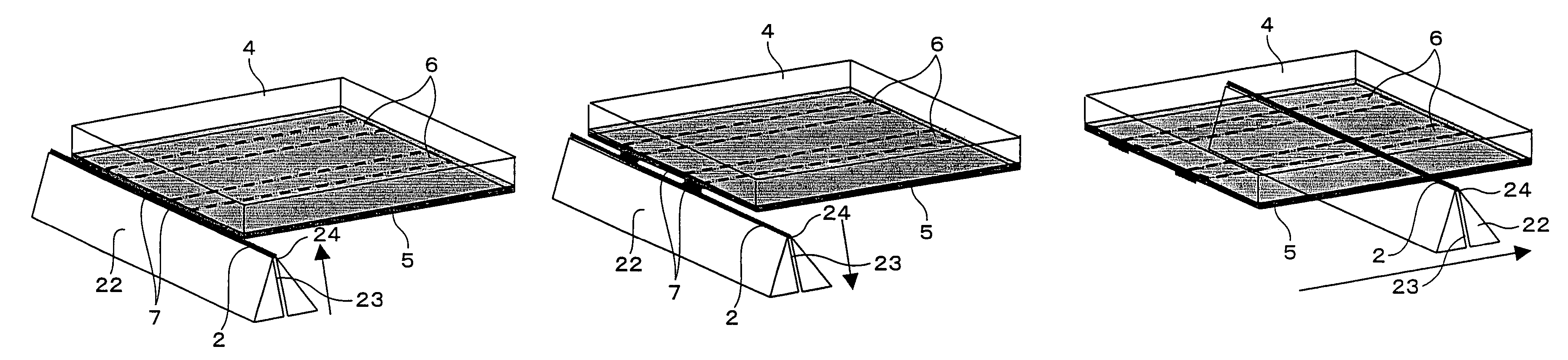
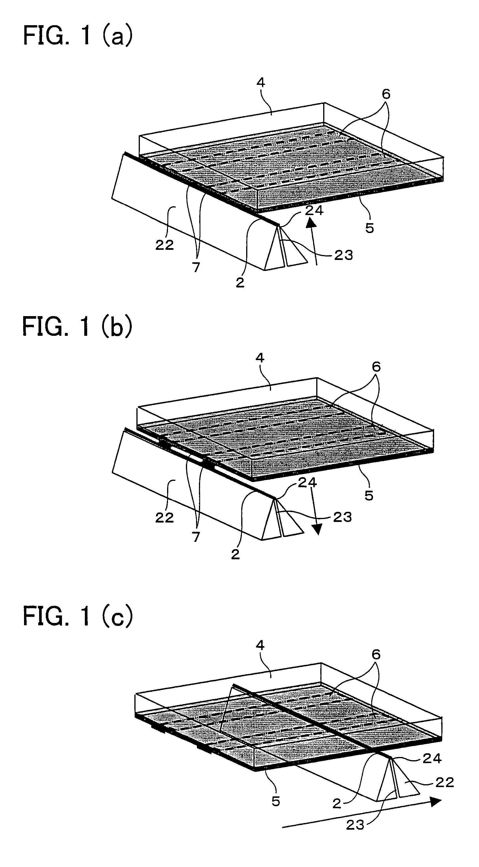
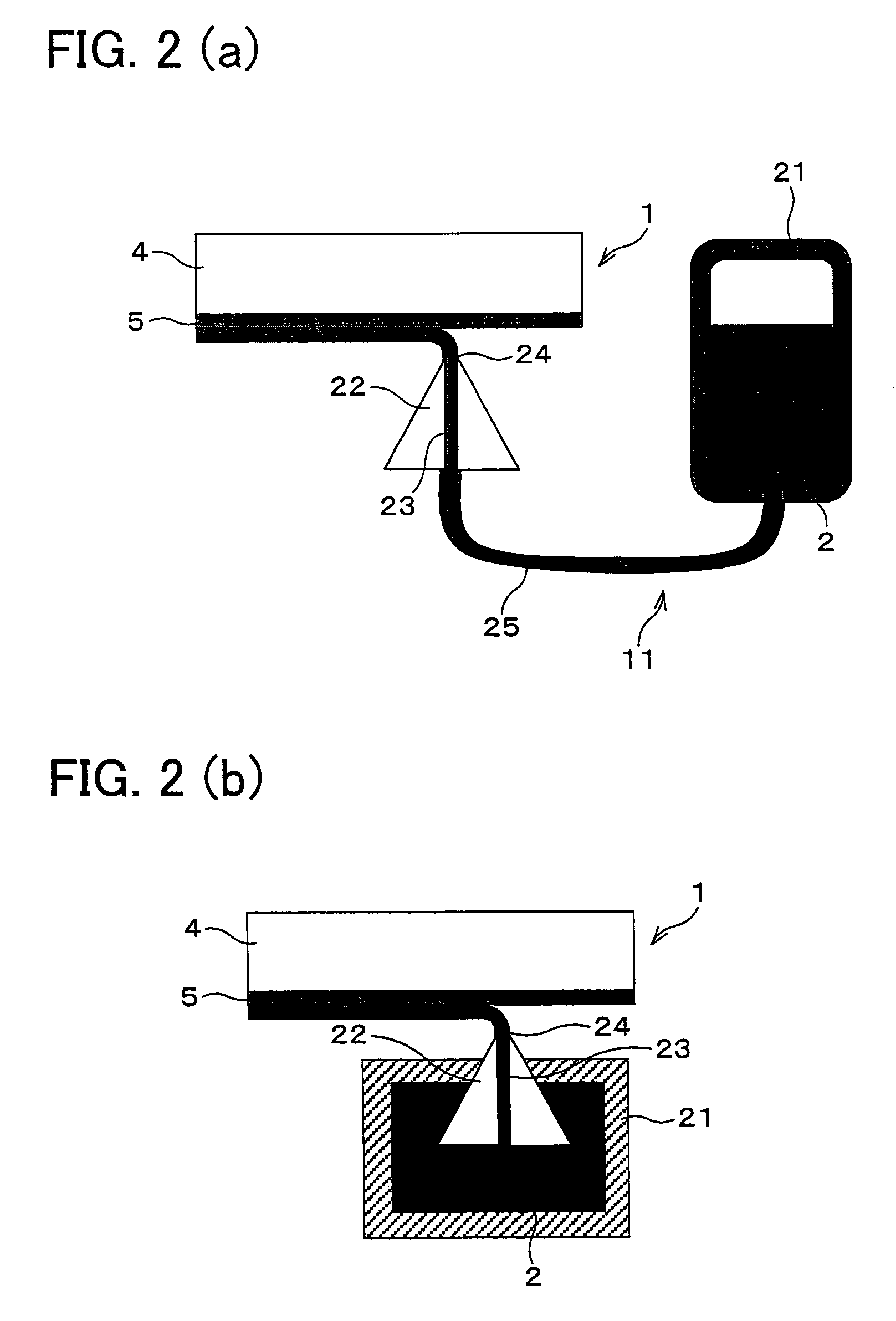
[0032]Next, a principle of manufacturing method of the color filter substrate 1 will be described with reference to FIGS. 1(a)-(c), FIGS. 2(a)-(b), and FIG. 4. Here, FIGS. 1(a)-(c) show contacting step and applying step in the present invention, and FIGS. 2(a)-(b) show a structure of an application device (coloring liquid supplying device) 11 used for the manufactur...


PUM


Abstract

A high-quality color filter substrate is manufactured simply and at low cost by using a color filter substrate manufacturing method of applying a coloring liquid to a substrate surface of a translucent substrate so as to form at least colored layer, including: contacting step of causing a coloring liquid supplied from a coloring liquid supplying section to bring into contact with areas showing lyophilic property to the coloring liquid and areas showing lyophobic property to the coloring liquid, both of the areas being formed on the substrate surface; and applying step of, after the contacting step, causing relative movement between the coloring liquid supplying section and the translucent substrate while continuously supplying a coloring liquid from the coloring liquid supplying section.

Description

[0001]This Nonprovisional application claims priority under 35 U.S.C. § 119(a) on Patent Application No. 2003 / 48092 filed in Japan on Feb. 25, 2003, the entire contents of which are hereby incorporated by reference.FIELD OF THE INVENTION[0002]The present invention relates to a color filter substrate for use in a liquid crystal display device, for example, and a color filter substrate manufacturing method.BACKGROUND OF THE INVENTION[0003]In recent years, application of a liquid crystal device to personal computers, portable information terminals, portable telephones, television sets, and others has been rapidly developed. For each of the liquid crystal devices, a color filter substrate is used to respond to a color display and generally forms a pattern of light's three primary colors of red (R), green (G), and blue (B).[0004]One conventional color filter substrate manufacturing method is a pigment dispersion method of forming a pattern of colored layers by applying a color resist ont...

Claims


Application Information

Patent Timeline
IPC IPC(8): G02B5/20B05C3/18B05C5/02B05C11/105B05D5/06G02F1/1335
CPCG02F1/133516
Inventor KISHIMOTO, SATORUTANAKA, KEIICHI
Owner SHARP KK
Why Eureka
Eureka Blog
Learn More