Piezoelectric resonator, filter, and duplexer
a resonator and piezoelectric technology, applied in piezoelectric/electrostrictive/magnetostrictive devices, piezoelectric/electrostriction/magnetostriction machines, impedence networks, etc., can solve the problem of partially lost energy essentially used for excitation of vibration in the piezoelectric body, easy to excite unwanted components, and suppress the occurrence of spurious components.
- Summary
- Abstract
- Description
- Claims
- Application Information
AI Technical Summary
Benefits of technology
Problems solved by technology
Method used
Image
Examples
first embodiment
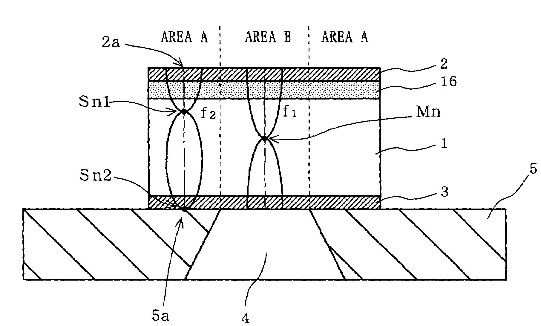
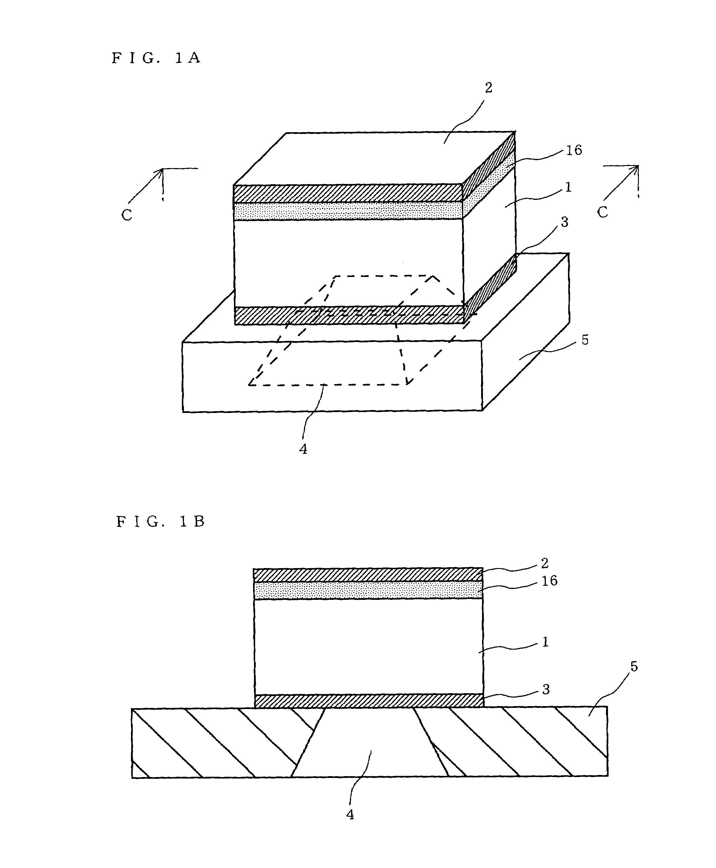
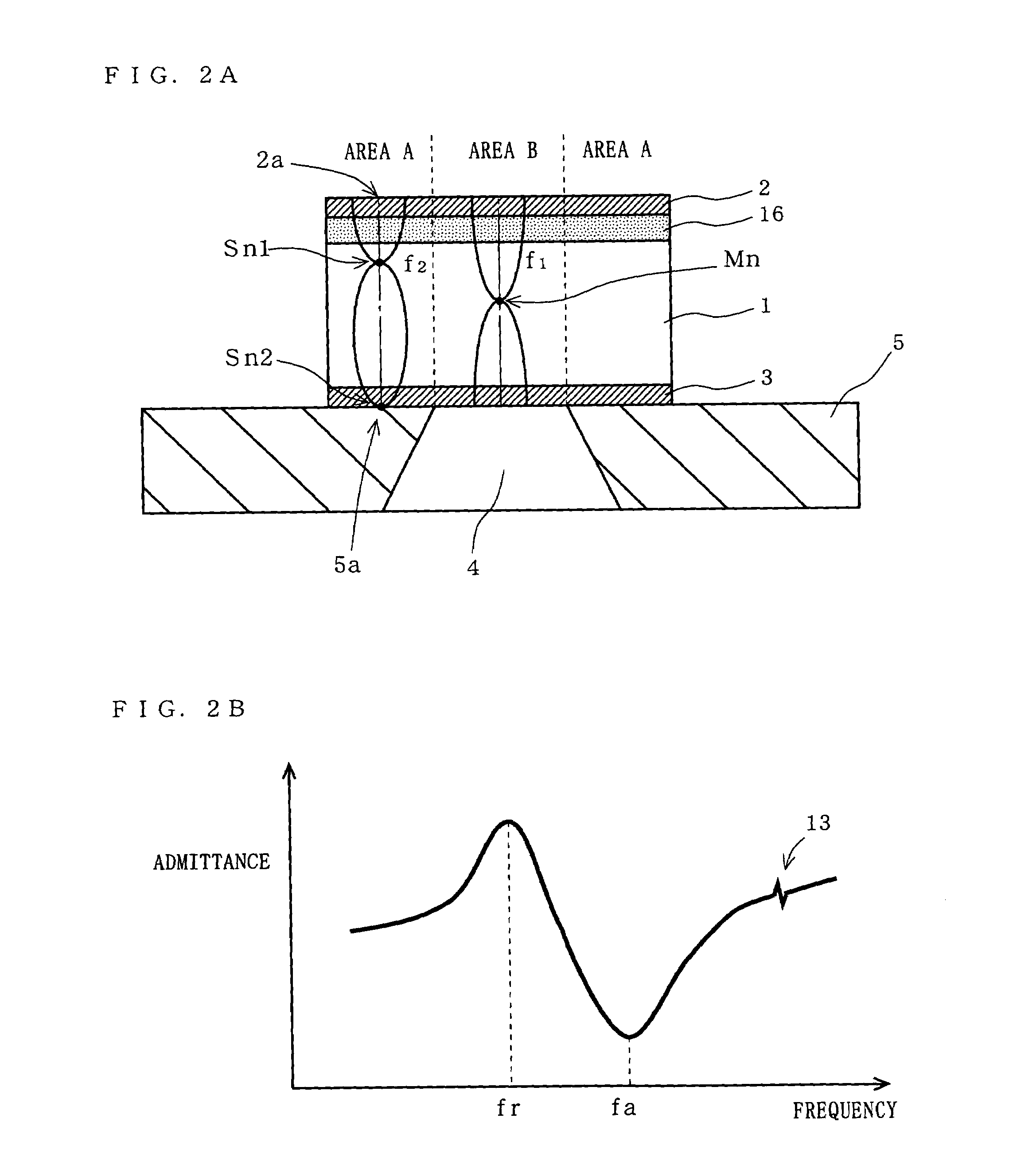
[0033]FIG. 1A is a perspective view showing an exemplary structure pattern of a piezoelectric resonator according to a first embodiment of the present invention. FIG. 1B is a cross-sectional view taken along line C-C shown in FIG. 1A. In FIGS. 1A and 1B, the piezoelectric resonator according to the first embodiment is structured such that on a substrate 5 having a cavity 4 provided therein, a lower electrode 3, a piezoelectric body 1, a spurious component control layer 16, and an upper electrode 2 are formed in this order from bottom up. The upper electrode 2 and the lower electrode 3 are composed of, for example, molybdenum (Mo). The piezoelectric body 1 is composed of, for example, a piezoelectric material such as aluminum nitride (AlN). The spurious component control layer 16 is composed of a metallic material, a dielectric material, or a piezoelectric material (which is different from the material of the piezoelectric body 1 included in the piezoelectric resonator). For example,...
second embodiment
[0052]A second embodiment is described with respect to another structure pattern of the piezoelectric resonator described in the first embodiment. Note that the structure pattern described in the second embodiment is merely an example, and various other structure patterns are conceivable.
[0053](1) In one exemplary structure, a spurious component control layer 6 is provided between the lower electrode 3 and the substrate 5, and the spurious component control layer 16 is provided between the upper electrode 2 and the piezoelectric body 1 (FIG. 4A). With this structure, it is possible to increase adhesive strength between the piezoelectric resonator and the substrate 5, while maintaining an effect of preventing any spurious component from occurring between the resonance frequency fr and the antiresonance frequency fa, whereby it is possible to increase the reliability of the piezoelectric resonator. Note that the spurious component control layer 6 and the spurious component control lay...
third embodiment
[0062]FIG. 5A is a cross-sectional view showing an exemplary structure pattern of a piezoelectric resonator according to a third embodiment of the present invention. In FIG. 5A, the piezoelectric resonator according to the third embodiment is structured such that on the substrate 5 having the cavity 4 provided therein, the lower electrode 3, the spurious component control layer 16, the piezoelectric body 1, the upper electrode 2, an additional piezoelectric body 51, and an additional electrode 52 are formed in this order from bottom up. The upper electrode 2, the lower electrode 3, and the additional electrode 52 are composed of, for example, molybdenum (Mo). The piezoelectric body 1 and the additional piezoelectric body 51 are composed of, for example, a piezoelectric material such as aluminum nitride (AlN). The spurious component control layer 16 is composed of a metallic material, a dielectric material, or a piezoelectric material (which is different from the material of the piez...
PUM
 Abstract
Description
Claims
Application Information
 - R&D
- Intellectual Property
- Life Sciences
- Materials
- Tech Scout
- Unparalleled Data Quality
- Higher Quality Content
- 60% Fewer Hallucinations
Browse by: Latest US Patents, China's latest patents, Technical Efficacy Thesaurus, Application Domain, Technology Topic, Popular Technical Reports.
© 2025 PatSnap. All rights reserved.Legal|Privacy policy|Modern Slavery Act Transparency Statement|Sitemap|About US| Contact US: help@patsnap.com


