Bandwidth allocation method in point-to-multipoint communication system

a communication system and bandwidth allocation technology, applied in data switching networks, frequency-division multiplexing, time-division multiplexing selection, etc., can solve the problems of inefficient use of transmission bandwidth, delay time for signal transmission, and inability to efficiently use transmission bandwidth, so as to shorten the delay time for starting and efficiently use transmission bandwidth.

Active Publication Date: 2007-08-21
NIPPON TELEGRAPH & TELEPHONE CORP
View PDF6 Cites 7 Cited by
  • Summary
  • Abstract
  • Description
  • Claims
  • Application Information

AI Technical Summary

Benefits of technology

[0044]According to the bandwidth allocation method (and the related program) of the present invention, the subsidiary units are grouped based on the round-trip propagation delay time L and a set of bandwidths for the allocation request signals are collectively allocated to each subsidiary unit group; therefore, every time the central unit receives allocation request signals (which are collectively issued from each group), the central unit can calculate the next bandwidths to be allocated to the relevant group. Therefore, the transmission bandwidth for transmitting data to the central unit can be efficiently used while shortening the delay time for starting the data transmission.

Problems solved by technology

In the above-explained conventional methods, it is impossible to efficiently use the transmission bandwidth while reducing the delay time for starting the transmission of the data signal (stored in the subsidiary unit) to the central unit.
However, owing to a section where bandwidths, which have not yet been allocated, are dispersed and thus the bandwidth allocation should be inefficiently performed (refer to the section indicated by reference numeral 200), or a section where a long bandwidth has already been allocated to a subsidiary unit and thus the delay time for starting the signal transmission of another subsidiary unit is increased (refer to the section indicated by reference numeral 300), the bandwidth cannot be efficiently used while reducing the delay time.

Method used


Image

  • Bandwidth allocation method in point-to-multipoint communication system
  • Bandwidth allocation method in point-to-multipoint communication system
  • Bandwidth allocation method in point-to-multipoint communication system

Examples


Embodiment Construction

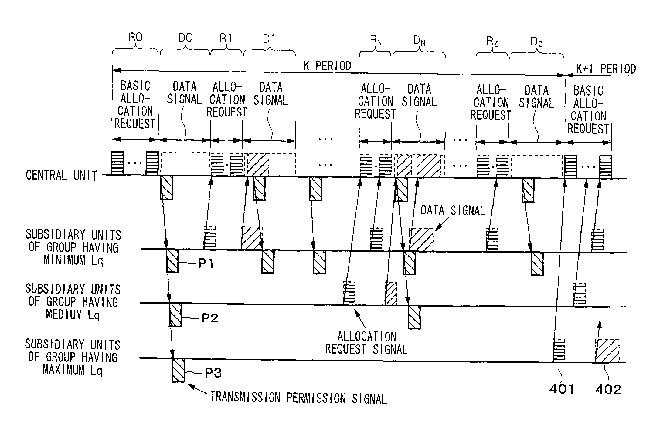
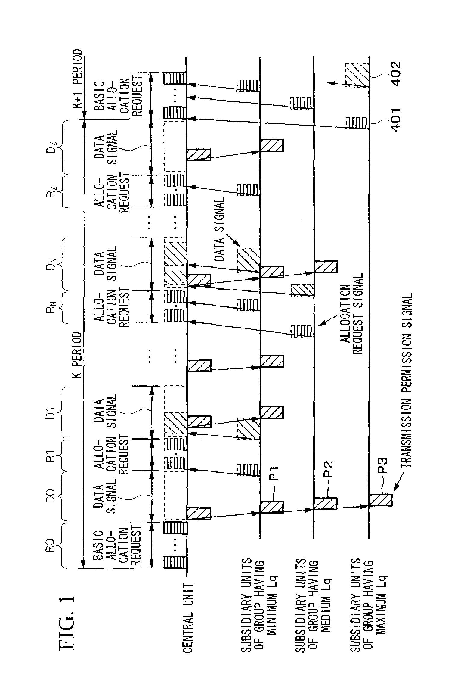
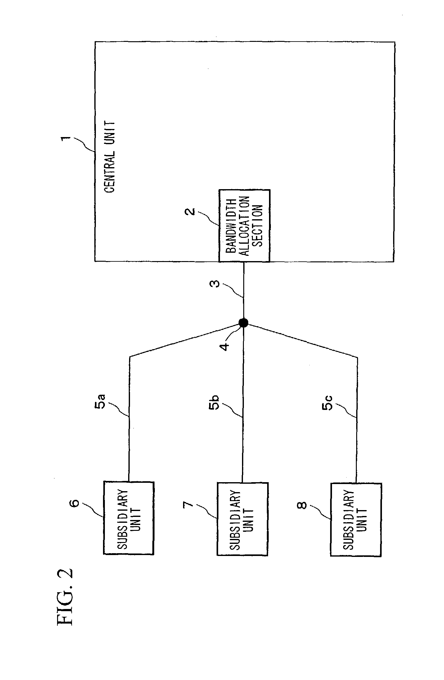
[0051]Hereinafter, a point-to-multipoint communication system, to which an embodiment of the bandwidth allocation method according to the present invention is applied, will be explained with reference to the drawings. The block diagram for showing the structure of the present communication system is basically the same as the conventional structure shown in FIG. 2; however, the function and operation of the bandwidth allocating section 2 is different.

[0052]Below, the function and operation of the bandwidth allocating section 2 will be explained with reference to FIG. 1. In FIG. 1, “BASIC ALLOCATION REQUEST” appended to some double-headed arrows indicates a basic allocation request signal bandwidth, “DATA SIGNAL” appended to some double-headed arrows indicates a data signal bandwidth, and “ALLOCATION REQUEST” appended to some double-headed arrows indicates an allocation request signal bandwidth, where these bandwidths will be explained below in detail.

[0053]First, similarly to the fir...


PUM


Abstract

A bandwidth allocation method used in a point-to-multipoint communication system, for efficiently using the bandwidth while shortening delay time. A central unit quantizes round-trip propagation delay times of subsidiary units, groups the subsidiary units, assigns the same quantized round-trip delay time to the same group, and allocates allocation request signal bandwidths to the subsidiary units of the same group when receiving allocation requests within a predetermined period. Based on the quantized round-trip delay time, the bandwidths are located as close as possible while the bandwidths do not temporally overlap with each other and as temporally ahead as possible. Data signal bandwidths are also allocated to the subsidiary units of the same group, based on the quantized round-trip delay time and requested amounts of data, in a manner such that the bandwidths are located as temporally ahead as possible but temporally behind in comparison with the allocation request signal bandwidths.

Description

BACKGROUND OF THE INVENTION[0001]1. Field of the Invention[0002]The present invention relates to a bandwidth allocation method used in a point-to-multipoint communication system in which a plurality of subsidiary units are connected to a single central unit via transmission paths and a transmission bandwidth is shared by the subsidiary units so as to send data to the central unit.[0003]2. Description of the Related Art[0004]Generally, in the point-to-multipoint communication system such as a LAN, a CATV network, a satellite communication network, or a subscriber access optical network, a central unit intercommunicates with a plurality of subsidiary units via a common communication path used in a coaxial communication, wireless communication, or optical fiber communication system.[0005]The PON transmission system is an example of the point-to-multipoint communication system, in which a central unit and subsidiary units are connected via optical fibers and an optical branch section.[0...

Claims


Application Information

Patent Timeline
Patent Type & Authority Patents(United States)
IPC IPC(8): H04J3/18H04L12/44H04J3/06H04J3/16H04L12/28H04L12/46H04Q11/04
CPCH04J3/1694H04L12/2861H04L12/4604H04L12/5695H04L47/15H04L47/283H04L47/781H04L47/822H04L47/826H04L47/828H04Q11/0478H04J3/0682H04L2012/561H04L2012/5632H04L2012/5679H04L47/70
Inventor OTA, NORIYUKIMIKI, NORIKI
Owner NIPPON TELEGRAPH & TELEPHONE CORP
Why Eureka
Try Eureka