Encoding device, decoding device, and system thereof utilizing band expansion information

a decoding device and band expansion technology, applied in the field of encoding and decoding processing of audio signals, can solve the problems of inability to reproduce high frequencies, inability to perform pseudo wide band processing, and inability to provide constant high-quality sounds. achieve the effect of reducing power consumption

Active Publication Date: 2007-08-21
PANASONIC INTELLECTUAL PROPERTY CORP OF AMERICA
View PDF10 Cites 40 Cited by
  • Summary
  • Abstract
  • Description
  • Claims
  • Application Information

AI Technical Summary

Benefits of technology

[0012]Accordingly, the selecting unit makes it extremely easy to make a selection between the second sound digital signal in the wide band to be outputted from the second reproducing unit and the first sound digital signal in the narrow band to be outputted from the first reproducing unit and to reproduce either of them.
[0016]Accordingly, an efficient reproduction of the wide band by the use of an intermediate signal as well as a selection according to mode information becomes possible.
[0018]Accordingly, unnecessarily performed processing can be stopped in an efficient manner when the second sound digital signal is not reproduced, which leads to reduction in the processing amount and further to reduction in power consumption.
[0020]Accordingly, while an efficient reproduction of the wide band and the narrow band based on the size information of a small amount of bit number becomes possible, reproduction with the reading of information for band expansion and processing for wide-band decoding being skipped also becomes possible just by referring to the size information when a high frequency signal is not reproduced, which results in a significant reduction in processing amount as well as in power consumption.
[0022]Accordingly, not only is it possible to make an extremely easy selection between a wide-band sound digital signal and a narrow-band sound digital signal in the decoding device, unnecessarily performed processing at the time of reproducing a PCM signal in the narrow band can also be skipped with extreme easiness.
[0025]Since the above effects are best demonstrated especially in such a battery-operated device as a mobile phone, the present invention is extremely feasible. Furthermore, in a device to decode encoded data for which such band expansion technology is applied, selection of whether to reproduce the second sound digital signal for which band expansion is performed or the first sound digital signal for which band expansion is not performed should be able to be made, considering power consumption of a device, listener's likings and so forth. Such function perfectly satisfies the inventors of the present invention who wish to make it possible to reproduce the first sound digital signal for which band expansion is not performed when receiving, for example, a voice broadcast such as news, in order to reduce power consumption.

Problems solved by technology

However, since an increased compression rate results in a lower upper limit frequency of the reproduction band, no high frequencies can be reproduced.
However, the constant provision of high-quality sounds ends up meaningless in many cases.
To put it another way, when listening to news, for example, there are fewer user requests for reproducing sounds for which pseudo wide band is created, meaning that it is impractical for a decoding device to perform pseudo wide band processing.
Furthermore, it results in a waste of battery power of a mobile phone and other devices embedded with a decoding device, which performs pseudo wide band processing even when there is no user request for this processing.

Method used


Image

  • Encoding device, decoding device, and system thereof utilizing band expansion information
  • Encoding device, decoding device, and system thereof utilizing band expansion information
  • Encoding device, decoding device, and system thereof utilizing band expansion information

Examples


first embodiment

THE FIRST EMBODIMENT

[0049]First, an explanation is provided for a decoding device which facilitates the achievement of the first and the second objects in an encoding device.

[0050]An encoding device according to the First Embodiment of the present invention is explained in subsequent paragraphs with reference to the figures.

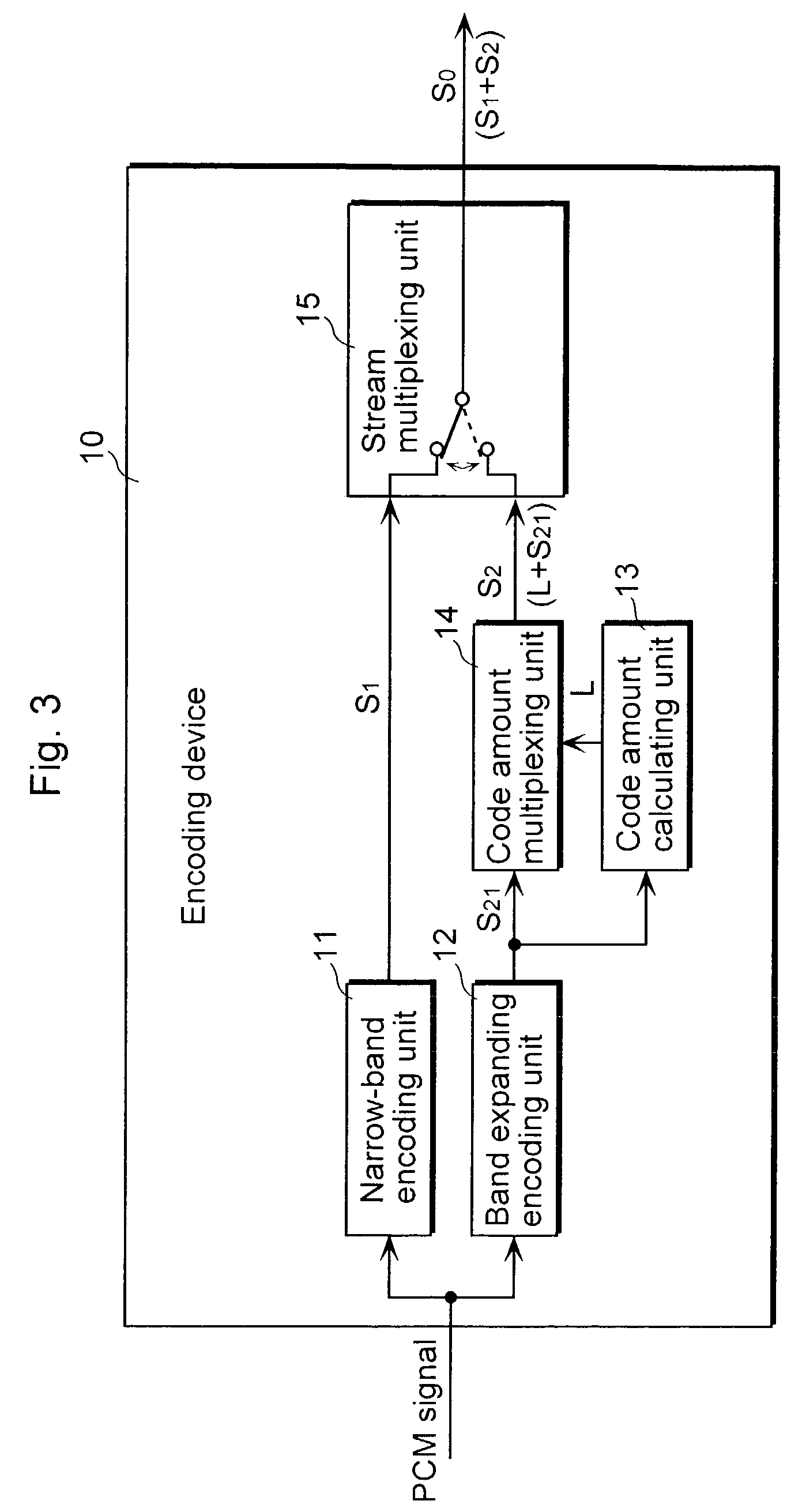
[0051]FIG. 3 is a block diagram illustrating a functional configuration of an encoding device 10 according to the First Embodiment.

[0052]The encoding device 10 is comprised of a narrow-band encoding unit 11, a band expanding encoding unit 12, a code amount calculating unit 13, a code amount multiplexing unit 14, and a stream multiplexing unit 15.

[0053]The narrow-band encoding unit 11 encodes an inputted PCM signal per frame (in AAC, 1024 samples in the audio data row) and generates a narrow-band bit stream S1 at low frequencies.

[0054]Based on the inputted PCM signal, the band expanding encoding unit 12 acquires band expansion information used for expanding the re...

second embodiment

THE SECOND EMBODIMENT

[0079]Next, an explanation is provided for a decoding device according to the Second Embodiment of the present invention with reference to the figures.

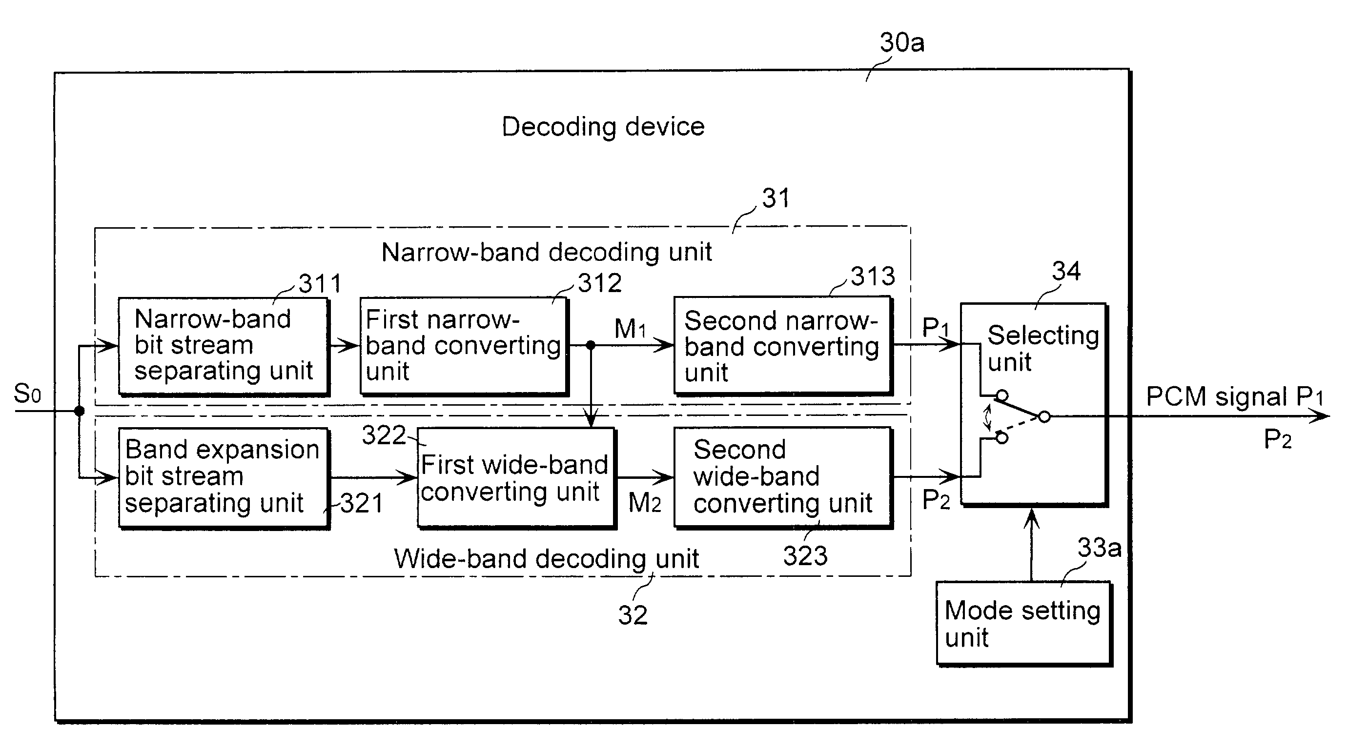
[0080]FIG. 8 is a block diagram showing a functional configuration of a decoding device 30a according to the Second Embodiment.

[0081]The decoding device 30a is comprised of a narrow-band decoding unit 31 which separates and decodes only the narrow-band bit stream S1 from the wide-band bit stream S0 outputted from the encoding device 10, a wide-band decoding unit 32 which separates and decodes only the band expansion bit stream S2, a selecting unit 34 which selects either a PCM signal in the narrow band (narrow-band PCM signal) decoded by the narrow-band decoding unit 31 or a PCM signal in the wide band (wide-band PCM signal) which is decoded by the wide-band decoding unit 32 and which expands to the narrow band by the amount of band expansion, and a mode setting unit 33a which sets a signal selection mode selected...

third embodiment

THE THIRD EMBODIMENT

[0103]Next, an explanation is provided for a decoding device 30b according to the Third Embodiment of the present invention.

[0104]FIG. 11 is a block diagram showing a functional configuration of a decoding device 30 according to the decoding device 30b of the present invention. Note that the same numbers as those used for the decoding device 30a in FIG. 8 are assigned to the corresponding parts in FIG. 11, in which detailed explanations are given only for the parts different from FIG. 8.

[0105]It should be noted that, in the decoding device 30a according to the Second Embodiment, the selecting unit 34 is responsible for the selection between a PCM signal P2 for which band expansion is performed and an output PCM signal P1 for which band expansion is not performed, but the decoding device 30b further includes a controlling unit 35 so as to reduce the processing amount at the time of outputting a PCM signal P1 for which band expansion is not performed.

[0106]The cont...


PUM


Abstract

A decoding device (30a) comprises a narrow-band decoding unit (31) operable to reproduce a PCM signal (P1) from a narrow-band bit stream included in a wide-band bit stream (S0), a wide-band decoding unit (32) operable to reproduce a PCM signal (P2) having a frequency band which is wider than that of the PCM signal (P1) reproduced by the narrow-band decoding unit (31) from the narrow-band bit stream and a band expanding bit stream included in the wide band bit stream (S0) and a selecting unit (34) operable to select either the PCM signal (P1) reproduced by the narrow-band decoding unit (31) or the PCM signal (P2) reproduced by the wide-band decoding unit (32), and to output the selected sound digital signal.

Description

TECHNICAL FIELD[0001]The present invention relates to encoding and decoding processing of audio signals, and more specially to an encoding device and a decoding device for creating a format of encoded data that facilitates decoding processing, and to a system utilizing such devices.BACKGROUND ART[0002]In response to popular demand for easy-to-enjoy music, a variety of technologies have been developed in recent years for performing compression encoding for audio signals such as voice and musical sounds at low bit rates and performing decompression decoding when reproducing these signals. A representative example of such technologies is the MPEG AAC system (to be abbreviated as “AAC” hereinafter) (Refer to: M. Bosi, et al.: “IS 13818-7 (MPEG-2 Advanced Audio Coding, AAC),” April, 1997)[0003]FIG. 1 is a diagram showing a frequency band to be encoded in the AAC system.[0004]However, since an increased compression rate results in a lower upper limit frequency of the reproduction band, no...

Claims


Application Information

Patent Timeline
Patent Type & Authority Patents(United States)
IPC IPC(8): G10L19/00G10L19/02G10L19/18G10L19/24
CPCG10L19/24G10L19/18G10L19/02
Inventor MIYASAKA, SHUJIISHIKAWA, TOMOKAZUSAWADA, YOSHIAKI
Owner PANASONIC INTELLECTUAL PROPERTY CORP OF AMERICA
Why Eureka
Try Eureka