Multi-column separation devices and methods

a separation device and multi-column technology, applied in the field of separation columns, can solve the problems of time-consuming flushing or cleaning steps not always yielding a completely clean column, false separation of every subsequent separation, and notoriously slow and laborious methods

Inactive Publication Date: 2007-08-28
AGILENT TECH INC
View PDF109 Cites 95 Cited by
  • Summary
  • Abstract
  • Description
  • Claims
  • Application Information

AI Technical Summary

Problems solved by technology

Various methods for packing a column body are known, although such methods are notoriously slow and laborious.
Due to the cost of conventional tubular chromatography columns, they are often re-used for many (e.g., typically about one hundred or more) separations.
However, this time-consuming flushing or cleaning step does not always yield a completely clean column 10.
This means that, after the first separation performed on a particular column, every subsequent separation may potentially include false results due to contaminants left behind on the column from a previous run.
Eventually, columns become fouled to the point that they are no longer useful, at which point they are removed from service and replaced.
One issue is evenly splitting or balancing the flow of mobile phase through each column of the multi-column system 50.
It would be desirable to provide the same flow conditions to each column of the multi-column system 50, but this is difficult to ensure for a number of reasons.
To begin with, it can be difficult to precisely match the inlet and outlet volumes to each column when tubing and conventional connectors are used since tube lengths and flow characteristics through different connectors often vary.
It can be difficult to provide the same flow characteristics to each individual column of a group of columns due to these variations in fluidic impedance, since fluid flow will be biased toward the column(s) and overall flow paths with the least fluidic impedance.
Thus, in a multi-column system employing a common set of pumps for performing gradient elution, the presence of a changing solvent concen

Method used


Image

  • Multi-column separation devices and methods
  • Multi-column separation devices and methods
  • Multi-column separation devices and methods

Examples


Embodiment Construction

A. Definitions

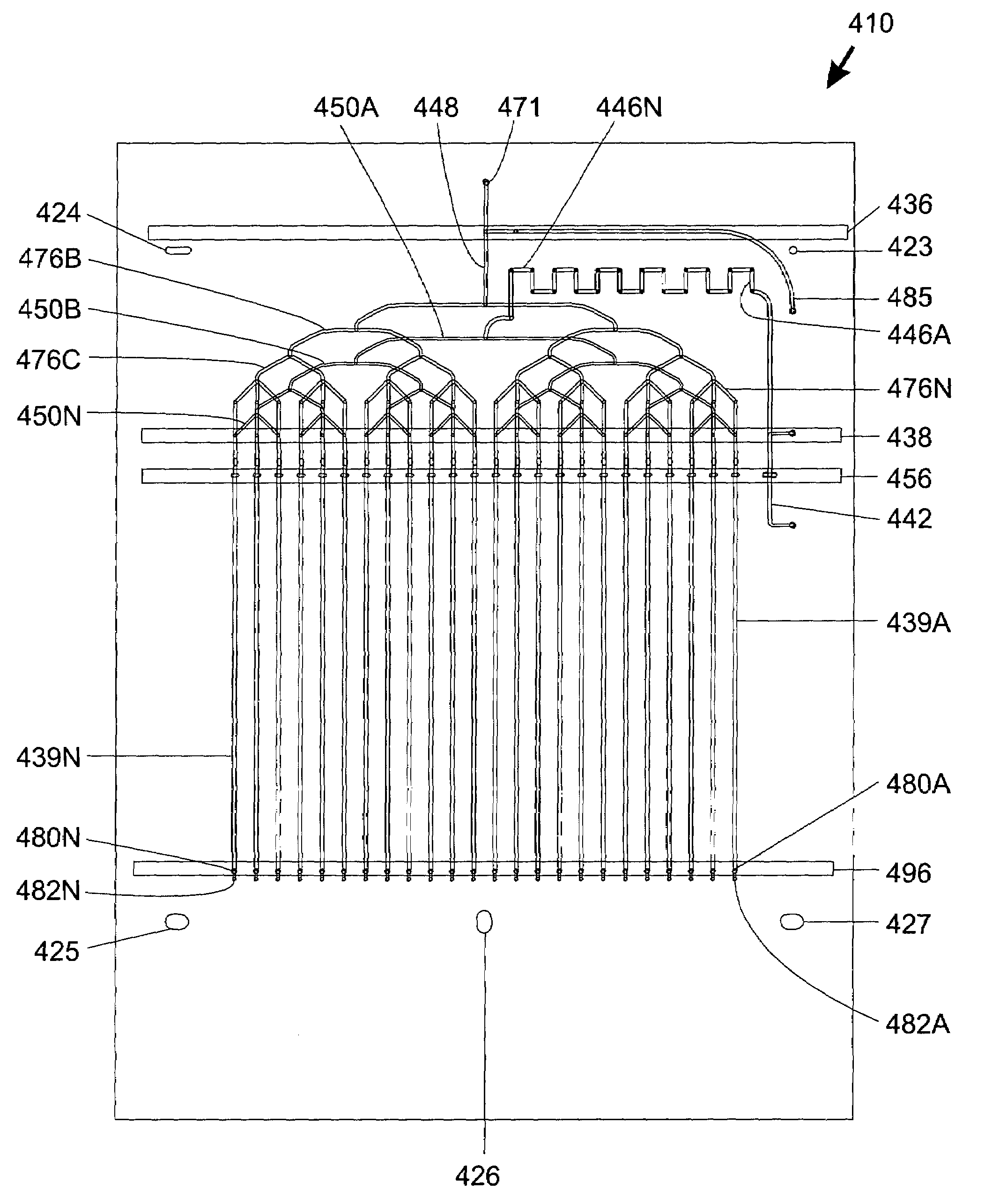
[0065]The term “batch-processed” as used herein refers to the state of being, or having been, produced in a common operation to impart common characteristics. Batch-processed separation columns containing particulate stationary phase material are preferably packed by supplying stationary phase to each column through a common inlet and a distribution manifold.

[0066]The terms “column” or “separation column” as used herein are used interchangeably and refer to a region of a fluidic device that contains stationary phase material and is adapted to perform a separation process.

[0067]The term “fluidic distribution network” refers to an interconnected, branched group of channels and / or conduits capable of adapted to divide a fluid stream into multiple substreams.

[0068]The term “frit” refers to a liquid-permeable material adapted to retain stationary phase material within a separation column.

[0069]The term “microfluidic” as used herein refers to structures or devices through wh...


PUM


Abstract

Chromatographic separation devices include multiple batch-processed columns joined by a body structure and adapted to perform parallel analyses. Both slurry-packed and monolithic column embodiments are provided. One or more liquid-permeable frits of various types may be used to retain stationary phase material within columns. A fluidic distribution network may be used to distribute stationary phase material and/or mobile phase solvents to multiple columns. Separation devices, including microfluidic embodiments, may be fabricated with various materials including polymers. Multi-column fabrication and separation methods are provided.

Description

STATEMENT OF RELATED APPLICATIONS[0001]This application cont-in-part and claims benefit of commonly assigned U.S. application Ser. No. 10 / 366,985 filed Feb. 13, 2003, now U.S. Pat. No. 6,923,907 which claims benefit of both U.S. Application Ser. No. 60 / 415,896 filed Oct. 3, 2002 and U.S. Application Ser. No. 60 / 357,683 filed Feb. 13, 2002.FIELD OF THE INVENTION[0002]The present invention relates to separation columns such as may be used for separating samples containing various chemical or biological species.BACKGROUND OF THE INVENTION[0003]Chemical and biological separations are routinely performed in various industrial and academic settings. For example, recent developments in the pharmaceutical industry and in combinatorial chemistry have exponentially increased the number of potentially useful compounds, each of which must be characterized in order to identify their active components and / or establish processes for their synthesis. To more quickly analyze these compounds, researc...

Claims


Application Information

Patent Timeline
IPC IPC(8): B01D15/08
CPCB01D15/1864G01N30/6043G01N30/6091B01D15/1885G01N30/603G01N30/6095
Inventor KARP, CHRISTOPH D.COVINGTON, JOSEPH F.GREGORI, MATTHEW M.HOBBS, STEVEN E.KOEHLER, JEFFREY A.O'CONNOR, STEPHEN D.PATEL, PAREN P.BEACH, SCOTT G.
Owner AGILENT TECH INC
Why Eureka
Try Eureka