
Electrohydrodynamic coating fluid delivery apparatus and method

a technology of electrohydrodynamic coating and fluid delivery, which is applied in the direction of fluid pressure measurement, liquid/fluent solid measurement, peptide measurement, etc., can solve the problems of inability to administer therapeutics to the target site the effectiveness of the device may be compromised, and the treatment may no longer be able to be administered in a uniform and homogeneous manner. , to achieve the effect of stable fluid flow and enhanced coating fluid flow stability

Inactive Publication Date: 2007-08-28
BOSTON SCI SCIMED INC
View PDF12 Cites 7 Cited by
  • Summary
  • Abstract
  • Description
  • Claims
  • Application Information

AI Technical Summary

Benefits of technology

This approach enables precise and uniform coating application on stents, maintaining high production efficiency while ensuring the coating fluid remains primed and ready for subsequent targets, even with low viscosity fluids, thereby enhancing the quality and consistency of the coating process.

Problems solved by technology

When the amount of coating is insufficient or is depleted through stripping of poorly adherent coating during manufacture or deployment within the patient's body, the device's effectiveness may be compromised and additional risks may be inured into the procedure.
For example, when the coating of the device includes a therapeutic, if some of the coating were removed during deployment, the therapeutic may no longer be able to be administered to the target site in a uniform and homogenous manner.
Similarly, if the therapeutic is ripped from the device it can reduce or slow down the blood flowing past it, thereby increasing the threat of thrombosis or, if it becomes dislodged, the risk of embolisms.
In certain circumstances, the removal and reinsertion of the device through a second medical procedure may be required where the coatings have been damaged or are defective.
Obtaining a uniform coating often becomes difficult when working with coating fluids with low viscosities.
In the case of electrohydrodynamic coating, when viscosity drops to a low viscosity, for example in the vicinity of one centipoise, it is difficult to control how much coating fluid is exposed to the electrohydrodynamic conditions.
Non-uniform coating application is also a problem at very low coating fluid flow rates, where difficulty controlling conventional pumping means can result in erratic fluid flow from the coating dispenser.
Lack of uniformity can be a problem as well where the coating fluid flow is applied to individual target work pieces in a start-stop fashion if the low viscosity coating fluid is given enough time to retreat from the coating fluid discharge point.
Conversely, if the electrohydrodynamic impulse is faster than the pump can deliver coating fluid to the dispensing head, insufficient coating may result when the amount of coating material at the dispensing head is depleted by the electrohydrodynamic pulse before the pump can supply an adequate volume of additional coating fluid to the dispensing head.
Under these conditions, it is difficult to achieve and sustain the required pump and electrohydrodynamic impulse coordination over the course of stent coating production runs.

Method used


Image

  • Electrohydrodynamic coating fluid delivery apparatus and method
  • Electrohydrodynamic coating fluid delivery apparatus and method
  • Electrohydrodynamic coating fluid delivery apparatus and method

Examples


first embodiment

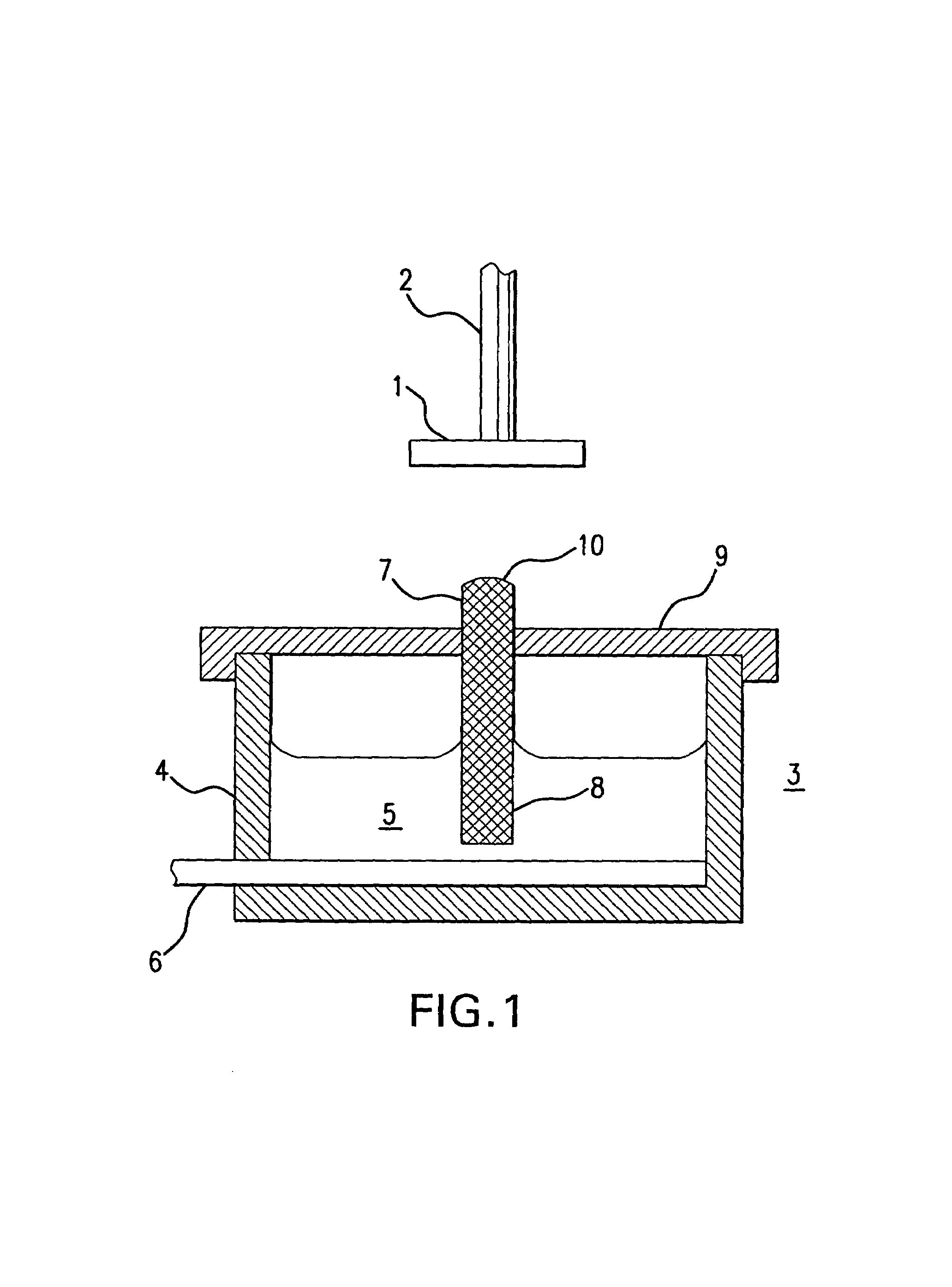
[0024]the present invention is illustrated in FIG. 1. In this embodiment, a target 1 to be coated with a coating fluid is held by target holder 2. Target 1 in this instance is a stent that is to be coated with a therapeutic material. In addition to holding stent 1 in a position suitable for coating application, stent holder 2 functions as a electrode, and is maintained at a first electrical potential. Stent holder 2 may hold stent 1 by any number of means, such as by the stent holders described in U.S. patent application Ser. No. 10 / 198,094 (the disclosure of which is hereby expressly incorporated by reference herein), and may be adapted for use with high-speed automated stent handling apparatus.

[0025]Directly beneath stent 1 is a coating fluid spray dispensing device 3, schematically illustrated in FIG. 1 as comprising a coating fluid reservoir 4 holding a quantity of coating fluid 5, a solution of a therapeutic material in either an organic solvent or water with low viscosity (pre...

fourth embodiment

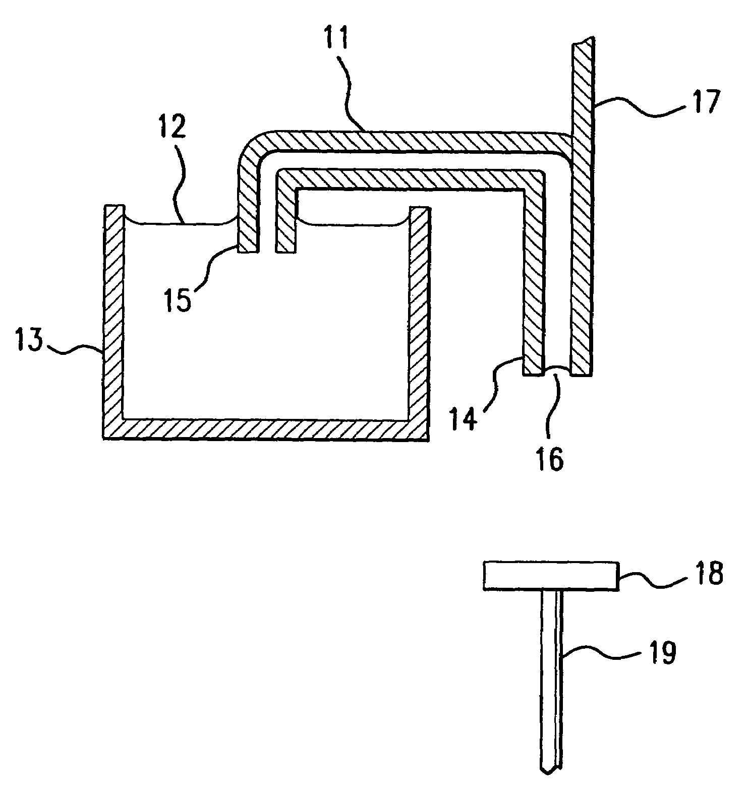
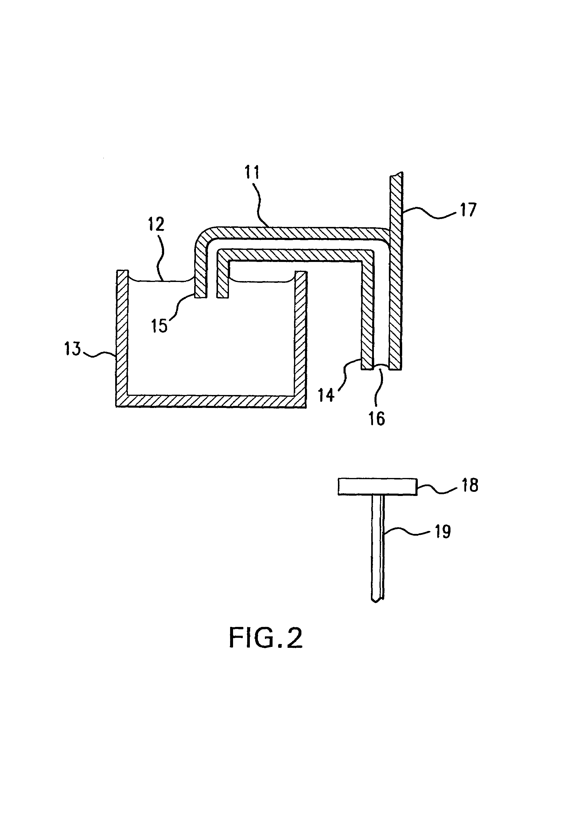
[0037]In the present invention illustrated in FIG. 4, siphon tube 11 is coupled to a float 21 that rests upon the surface of the coating fluid in reservoir 13, and the electrical connection to the siphon tube electrode (not shown) is sufficiently flexible to permit siphon tube 11 to move vertically as the coating fluid level in reservoir 13 changes. If necessary, a counterweight 22 may be placed on or in float 21 to help counteract any tendency for siphon tube 11 to tip the float over.

[0038]With this embodiment, float 21 maintains siphon tube inlet end 15 at a constant depth relative to the surface of the coating fluid in reservoir 13, and accordingly maintains a constant height difference between the level of the coating fluid in reservoir 13 and siphon tube dispensing end 14. This latter fixed height difference results in the hydrostatic pressure at dispensing end 14 remaining constant as the depth of the coating fluid within the reservoir decreases, thereby improving the consiste...


PUM

PropertyMeasurementUnit
thickaaaaaaaaaa
thickaaaaaaaaaa
thickaaaaaaaaaa

Abstract

An apparatus and method for improved control of low viscosity fluid flow during electrohydrodynamic spray deposition of the fluid to coat small targets, such as medical devices like stents. The apparatus includes a target holder which applies a first electrical potential to a target, a coating fluid transporter such as a wick, a siphon tube or a siphon tube with a wick therein along which the coating fluid flows from a reservoir to a dispensing end of the transporter, and an electrode which applied a second electrical potential to the coating fluid sufficient to cause the coating fluid to be attracted from the dispensing end of the transporter toward the target. This provides a target coating apparatus with highly self-regulating coating fluid flow characteristics despite the low viscosity of the coating fluid, while producing highly consistent and uniform target coatings.

Description

FIELD OF THE INVENTION[0001]The present invention generally regards an apparatus and method for application of coatings to small devices, such as the application of therapeutic and protective coatings to stents. More specifically, the present invention pertains to an apparatus and method for improved control of very low viscosity coating fluid flow during electrohydrodynamic spray deposition of coatings onto targets such as medical stents.BACKGROUND[0002]Medical implants are used for innumerable medical purposes, including the reinforcement of recently re-enlarged lumens, the replacement of ruptured vessels, and the treatment of disease such as vascular disease by local pharmacotherapy, i.e., delivering therapeutic drug doses to target tissues while minimizing systemic side effects. Such localized delivery of therapeutic agents has been proposed or achieved using medical implants which both support a lumen within a patient's body and place appropriate coatings containing absorbable ...

Claims


Application Information

Patent Timeline
Patent Type & Authority Patents(United States)
IPC IPC(8): B05D1/04A61L31/10A61L31/16B05B5/025B05B5/08B05B5/10B05B5/16
CPCA61L31/10A61L31/16B05B5/025B05B5/08B05B5/16B05B5/10
Inventor BOULAIS, DENNIS R.STENZEL, ERIC B.
Owner BOSTON SCI SCIMED INC
Learn More