
Systems and methods for measuring fluid properties

a technology of fluid properties and systems, applied in chemical methods analysis, instruments, transportation and packaging, etc., can solve problems such as insufficient dosage, inconvenient flow, bleeding complications, etc., and achieve the effect of accurate measurement of fluid properties

Active Publication Date: 2007-08-28
THROMBODYNE INC
View PDF10 Cites 22 Cited by
  • Summary
  • Abstract
  • Description
  • Claims
  • Application Information

AI Technical Summary

Benefits of technology

[0006]It has been recognized that there is a need to develop systems and methods that provide good mixing properties, without substantial damage to blood aggregates or other fluid properties to be measured. At the same time, such a system can also provide streamlined flow in a distinct region for accurate measurement of a fluid property. The present invention addresses the limitations of previous methods and presents fluid measurement devices and methods that enable more reliable assessment of platelet function, or in the case of other fluids, more reliable assessment of a desired fluid property.
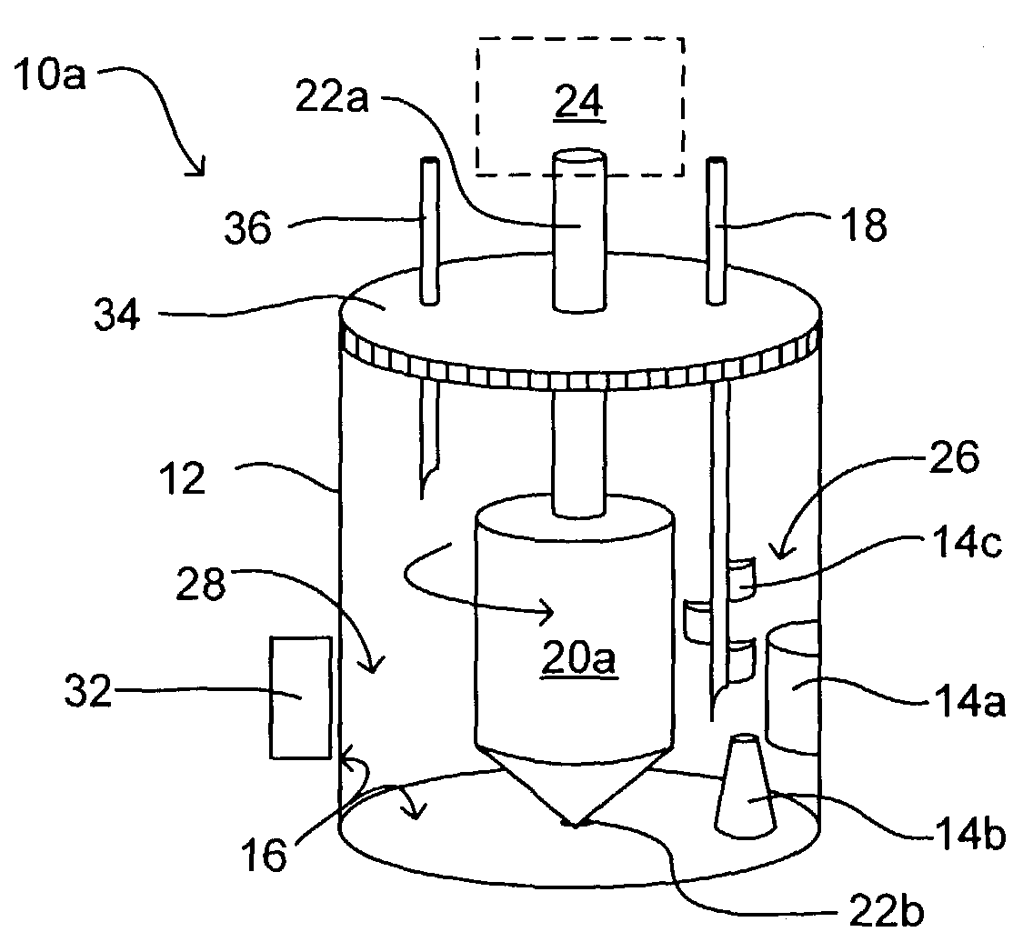
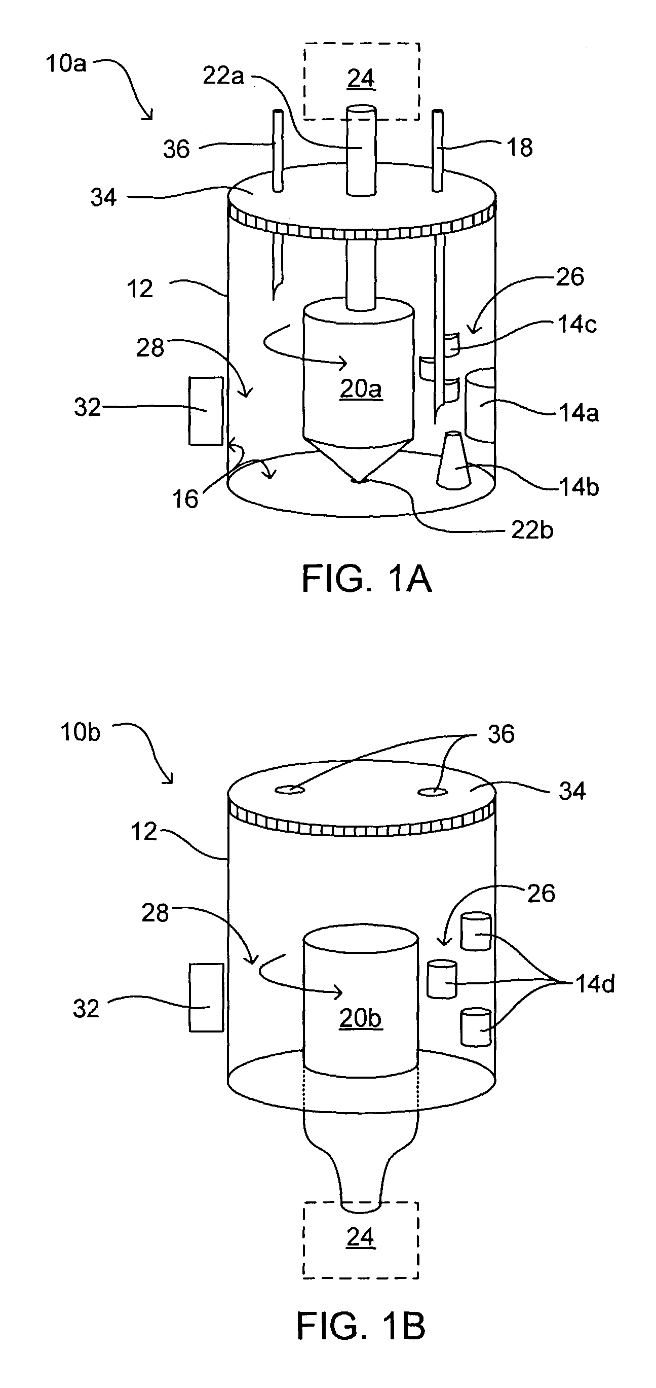
[0011]In another detailed aspect of the present invention, the mixing region can be produced by a stationary obstruction that interrupts more streamlined flow.

Problems solved by technology

Excess dosage of the antiplatelet drugs can result in bleeding complications because the platelet function is over-suppressed, while insufficient dosage can fail to prevent acute thrombosis and clotting due to insufficient suppression of platelet function.
However, most of these methods and devices create flow that is not conducive to enabling certain detection modalities of platelet aggregation, particularly for light scattering methods.
Many methods utilize mechanical mixing which often damages or otherwise alters fluid characteristics.
However, the compression of a flow conduit containing blood by means of rollers often disfigures platelet aggregates, damages red cells, and alter their characteristics.
Thus, the ergonomics of such designs can be undesirable, and loading of the blood sample and / or the chemical stimulus that causes platelet aggregation can be cumbersome.
These limitations detrimentally influence the quality and consistency of platelet aggregation, which in turn adversely affects the reproducibility and reliability of the measurement of platelet function.
Other methods include designs that present relatively good flow patterns for measurement using light scattering techniques, but do not provide significant mixing that induces more thorough and consistent platelet aggregation.

Method used


Image

  • Systems and methods for measuring fluid properties
  • Systems and methods for measuring fluid properties
  • Systems and methods for measuring fluid properties

Examples


example 1

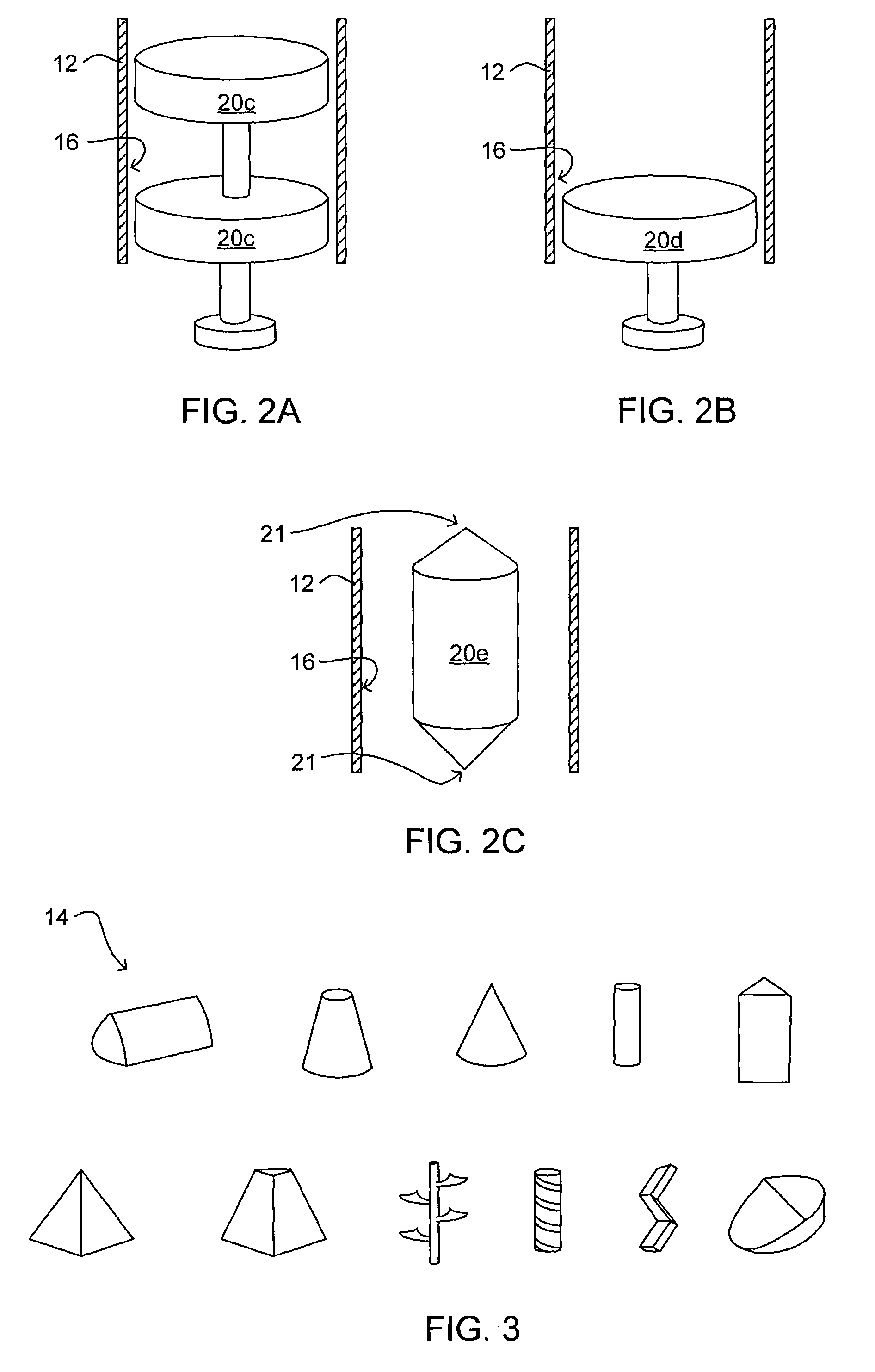
[0056]A cylindrically shaped fluid container having an inner diameter of 11 mm, a height of 20 mm, and a wall thickness of 2 mm was obtained. The fluid container is formed of a polycarbonate, coated on the inner surface with a non-tacky coating to increase compatibility with blood. A cylindrical cap, having an 11 mm inner diameter and 20 mm height made of the material DELRIN™ was fitted to substantially seal the inner diameter of the fluid container. The cap had a 4 mm diameter hole in the center, extending entirely through the height of the cap, i.e., 20 mm, and includes a side notch measuring 5 mm by 5 mm (also extending the entire length of the cap). The rotor included a cylindrical shaft 24 mm in length and 4 mm in diameter, and a rotor body that was 6 mm in diameter and 6 mm in length. The bottom of the rotor body included a sharp pointed tip with a 30° angle similar to rotor 20a shown in FIG. 1A. A disruption member was present that included a cylindrical protrusion measuring ...

example 2

[0058]A fluid container including two identical reservoirs connected by an elongated conduit was formed, similar to the embodiment shown in FIG. 4A. The base of each reservoir was 20 mm in diameter and the length of each reservoir was 30 mm. At 20 mm below each base, the diameter gradually decreased to 3 mm at the top. The reservoirs were made of polypropylene, coated with a non-adhesive coating to increase blood compatibility. At the base of each reservoir was a piston that was 20 mm in diameter and 10 mm in length. The movement of the piston up and down into each respective reservoir was propelled by a linear actuator. The narrow ends of the reservoirs were connected with a conduit of polyvinyl chloride tubing having a 3 mm inner diameter, a 1.5 mm wall thickness, and 40 mm length. One reservoir contained a 2 mm circular injection port and a self-sealing rubber diaphragm 5 mm from the top.

[0059]A volume of 1 ml of whole blood was transferred into one of the two reservoirs prior to...


PUM

PropertyMeasurementUnit
internal volumeaaaaaaaaaa
thicknessaaaaaaaaaa

Abstract

A method for measuring properties of a fluid including placing a quantity of fluid in a container; inducing flow in the fluid wherein the flow is substantially streamlined in at least a measuring region of the container, and wherein the fluid is recirculated through the measuring region; creating a mixing region separate from the measuring region sufficient to substantially mix the fluid; and measuring a property of the fluid in the streamlined region. The invention is of particular interest in the assessment of blood platelet function. The method provides specific localized regions of thorough mixing that enable reproducible platelet aggregation, and also provides specific localized regions of streamlined flow that enable certain modalities of assessing aggregation. Both of these regions of flow are induced such that damage to platelet aggregates and other blood components is minimized.

Description

FIELD OF THE INVENTION[0001]The present invention relates generally to methods for measuring fluid properties, such as fluid suspension properties. More particularly, the present invention relates to measuring blood platelet function.BACKGROUND OF THE INVENTION[0002]Currently, there are over 2 million hospitalizations and nearly 10 million visits to physicians that are associated with coronary heart disease in the United States every year. A majority of these patients receive some form of antiplatelet therapy, e.g. Aspirin, Plavix, etc., to prevent acute thrombosis and clotting associated with vascular interventions, such as angioplasty, or implants, such as coronary stents. Excess dosage of the antiplatelet drugs can result in bleeding complications because the platelet function is over-suppressed, while insufficient dosage can fail to prevent acute thrombosis and clotting due to insufficient suppression of platelet function. Thus, it would be valuable to assess platelet function i...

Claims


Application Information

Patent Timeline
Patent Type & Authority Patents(United States)
IPC IPC(8): G01N33/86B01F27/93B01F27/94G01N11/14G01N15/00
CPCB01F7/26B01F7/28B01F11/0071B01F15/00915G01N15/0205G01N33/4905G01N33/86G01N11/14B01F7/00491Y10T436/117497G01N2015/0092B01F27/1155B01F27/94B01F27/93B01F31/65B01F35/5312
Inventor ZHENG, YUSUKAVANESHVAR, SIVAPRASADTHEKKEDATH, RAMACHANDRAN
Owner THROMBODYNE INC
Learn More