
Controller for wire electric discharge machine

a wire electric discharge machine and control board technology, applied in the direction of electric circuits, instruments, manufacturing tools, etc., can solve the problems of insufficient accuracy of feed, inability to perform finish machining with sufficient accuracy, and difficulty in choosing a proper gain, etc., to achieve high accuracy

Active Publication Date: 2007-08-28
FANUC LTD
View PDF10 Cites 9 Cited by
  • Summary
  • Abstract
  • Description
  • Claims
  • Application Information

AI Technical Summary

Benefits of technology

The present invention provides a controller for a wire electric discharge machine that can perform stable finish machining with high accuracy even at a corner portion of the machining path where a large width of part remains after previous machining. The controller includes a machining rate determining means, a motion control means, and a switching means. The machining rate determining means determines the amount of removed part of the workpiece in a predetermined time period. The motion control means controls the motion of the wire electrode relative to the workpiece in accordance with the determined machining rate. The switching means switches the set value of the motion rate for a reference value of the machining rate when the machining rate increases or decreases beyond certain thresholds. This allows for a smooth finish machining process even at corner portions of the machining path.

Problems solved by technology

Hence, the constant average machining voltage method is not always suitable for finish machining after the first cutting, namely second cutting and subsequent machining, in which electric discharge machining is performed using a smaller electric discharge pulse current to improve surface roughness and accuracy.
In the constant average machining voltage feed control, feeding cannot be performed with sufficient accuracy, since change in average machining voltage cannot reflect change in removal width (width of a part to be removed) accurately.
Further, it is very difficult to choose a proper gain according to chance in average machining voltage corresponding to change in removal width.
Hence, the conventional control has a problem that it cannot provide stable surface accuracy repeatedly.
Also in the constant feed speed machining, it is difficult to improve the accuracy of machining.
However, there remains a problem.
However, in a region such as a corner portion in which the amount of machining is very large, it is difficult to perform control on the basis of the normal ratio of the distance of movement to the amount of machining.
In such case, machining is unstable such that short circuits are produced repeatedly, and cannot provide high form accuracy.

Method used


Image

  • Controller for wire electric discharge machine
  • Controller for wire electric discharge machine
  • Controller for wire electric discharge machine

Examples


Embodiment Construction

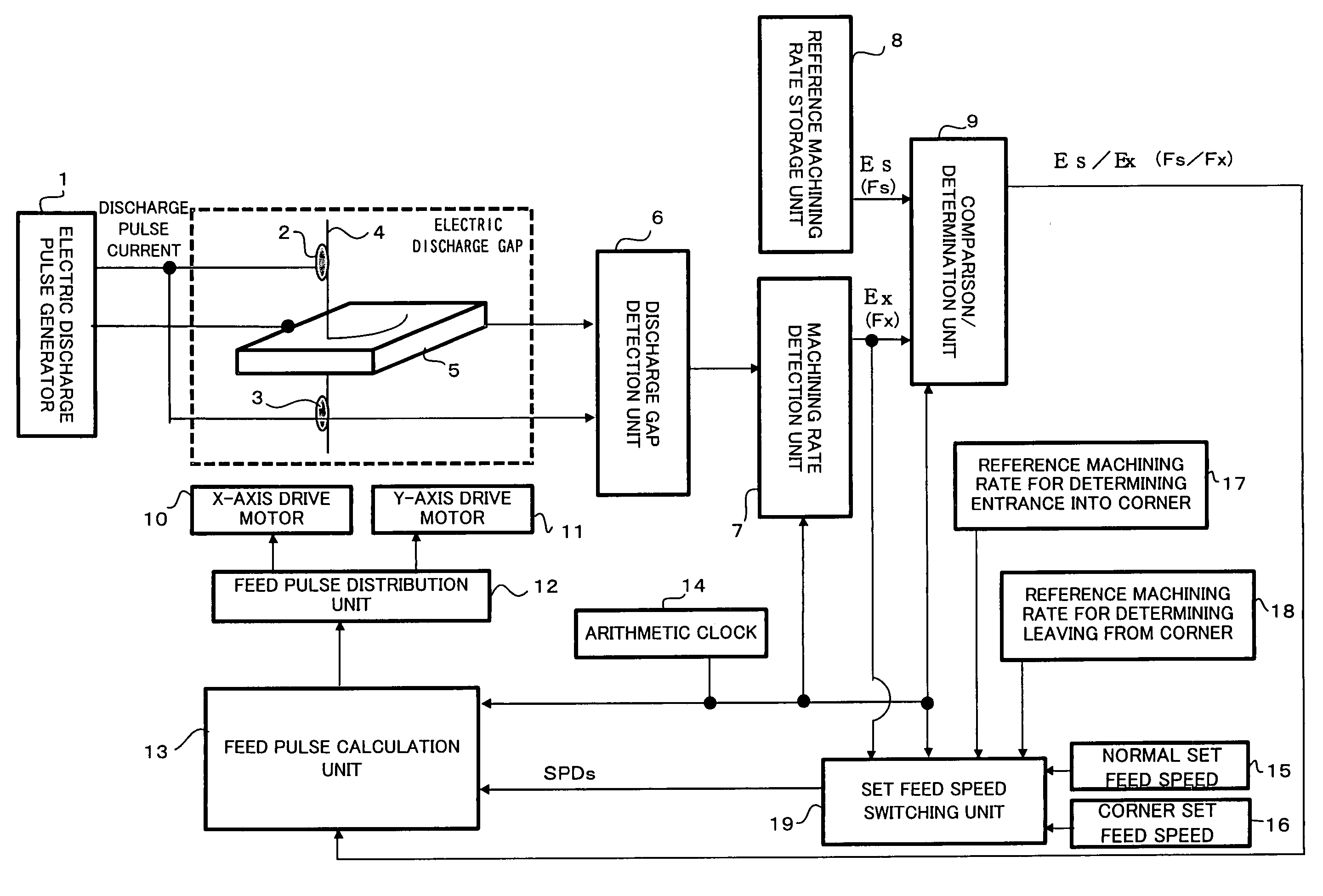
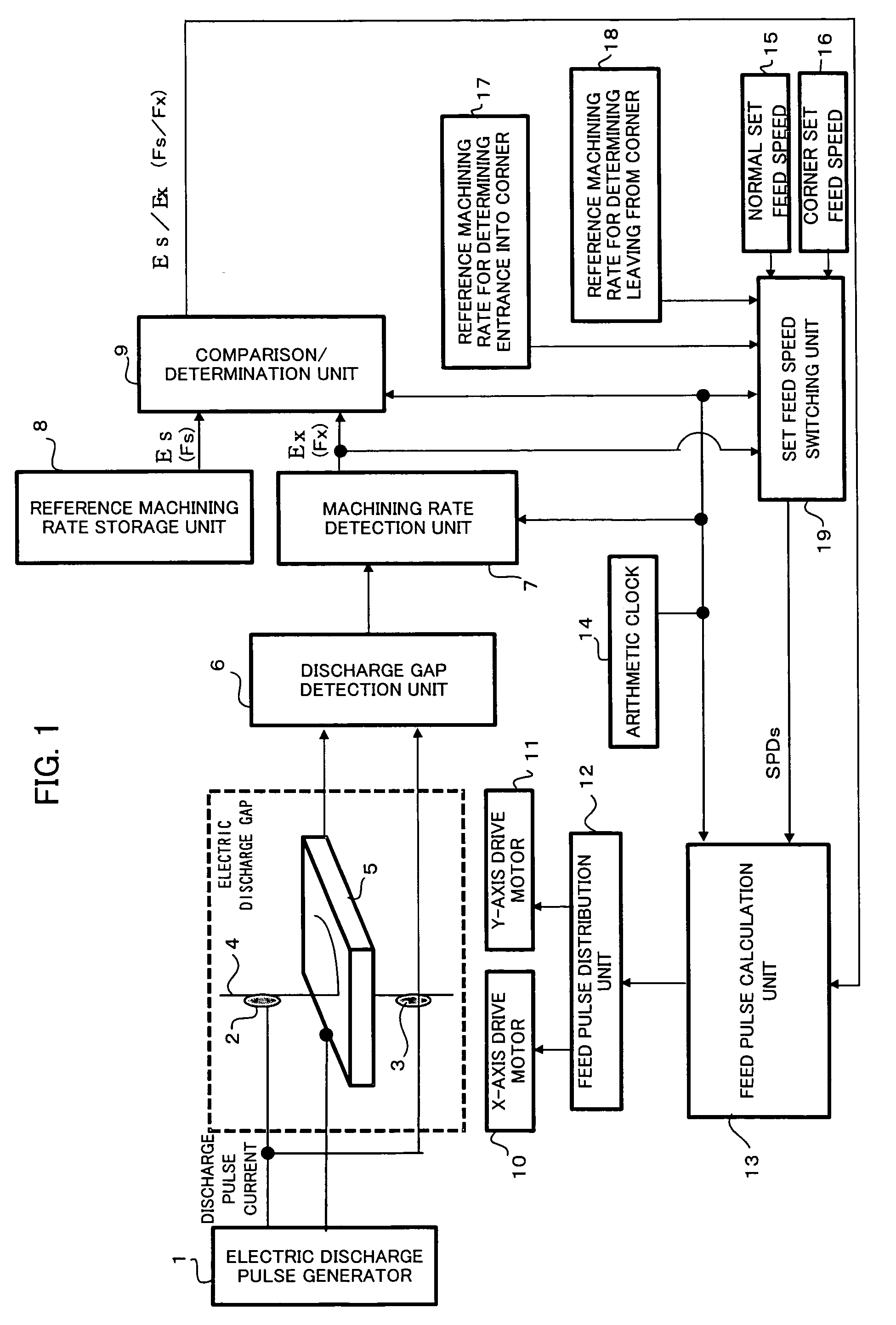
[0048]FIG. 1 is a block diagram showing relevant parts of a controller for a wire electric discharge machine in one embodiment of this invention. An electric discharge pulse generator 1 is for applying an electric discharge pulse voltage across a gap between a wire electrode 4 and a workpiece 5 for electric discharge machining, and comprises a direct-current power source, a circuit including a switching element such as a transistor, a capacitor charging / discharging circuit, etc. Conducting brushes 2 and 3 are for transmitting electricity to the wire electrode 4, and connected to one of the terminals of the electric discharge pulse generator 1. The workpiece 5 is connected to the other terminal of the electric discharge pulse generator 1. The electric discharge pulse generator 1 applies a pulse voltage between the traveling wire electrode 4 and the workpiece 5. A table (not shown) on which the workpiece 5 is mounted is driven by an X-axis drive motor control device 10, a Y-axis drive...


PUM

PropertyMeasurementUnit
drop voltageaaaaaaaaaa
electric discharge repetition numberaaaaaaaaaa
electric dischargeaaaaaaaaaa

Abstract

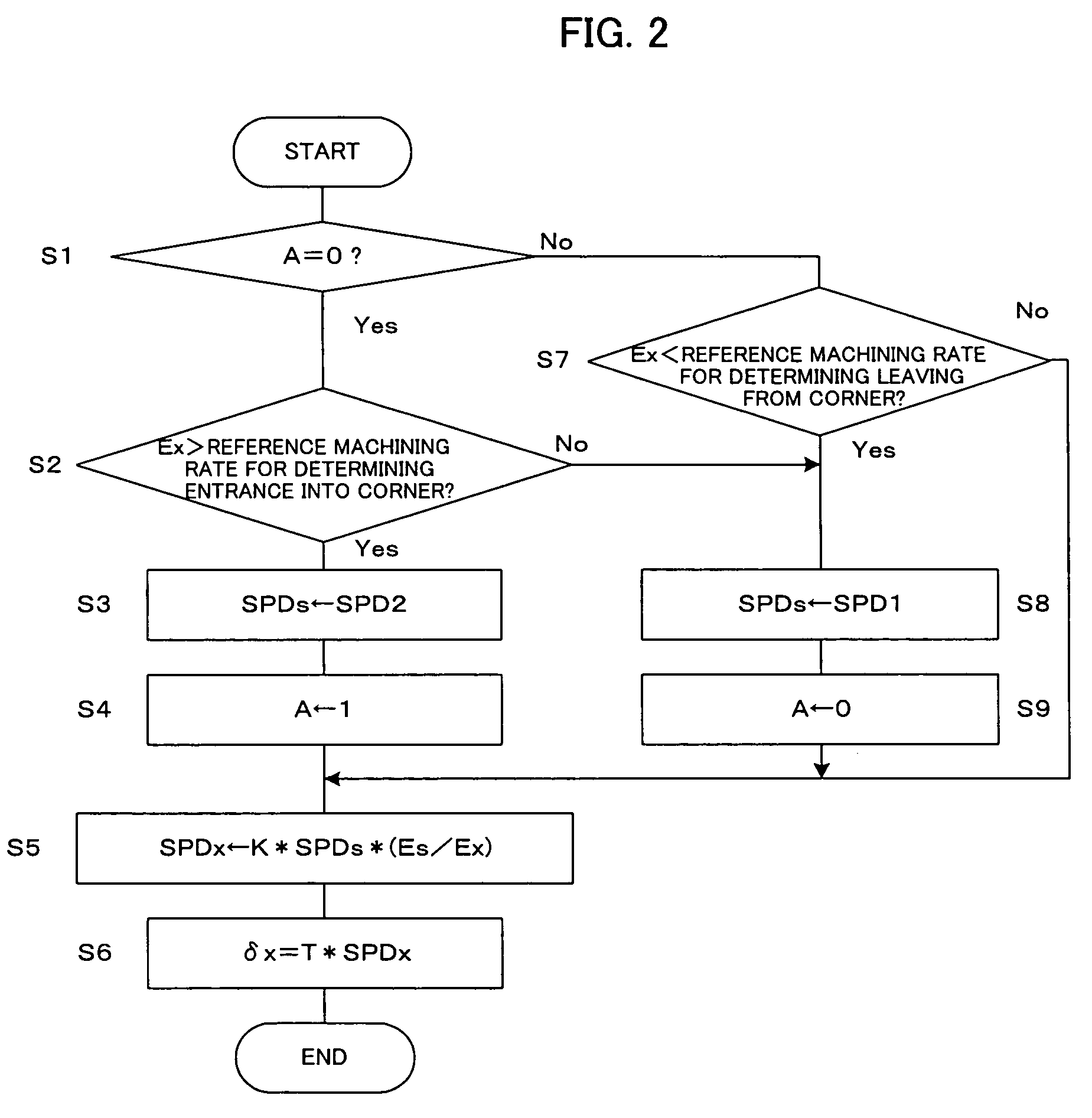
A controller for a wire cut electric discharge machine which can provide stable finish machining and corner-region machining with high corner-form accuracy. An electric discharge gap detection device detects a voltage between a wire electrode and a workpiece. A machining rate detection device obtains an average machining voltage and a drop voltage value Ex which is a difference between the obtained average machining voltage and a no-load voltage. A comparison device obtains the ratio Es / Ex between a reference drop voltage value Es stored in a reference machining rate relative value storage device and the obtained drop voltage value Ex. In machining of a corner portion, when the drop voltage value Ex exceeds a entrance-into-corner determination reference machining rate, a set feed speed switch device supplies a corner set feed speed, and when the machining of the corner portion finishes, so that the drop voltage value Ex decreases to a leaving-from-corner determination reference machining rate or lower, the set feed speed switch device supplies a normal set feed speed. A feed pulse calculation device obtains a feed speed which makes the rate of machining constant, on the basis of the ratio Es / Ex and the supplied feed speed, to thereby drive motors. Since the rate of machining is kept constant, the surface accuracy of finish machining is high and stable machining can be performed.

Description

BACKGROUND OF THE INVENTION[0001]1. Field of the Invention[0002]The present invention relates to a controller for a wire electric discharge machine, and particularly to a controller for controlling the wire electric discharge machine to perform finish machining of a second cut and subsequent cuts.[0003]2. Description of Related Art[0004]In the wire electric discharge machine, as methods of controlling the feeding of a wire electrode relative to a workpiece, a constant average machining voltage method and a constant feed speed method are known. The constant average machining voltage method controls the feed speed such that the average machining voltage across a gap between the workpiece and the wire electrode is constant, in order to increase the speed of first cutting, namely contour cutting first performed on the workpiece, and prevent the break of the wire electrode due to concentrated electric discharges. Hence, the constant average machining voltage method is not always suitable...

Claims


Application Information

Patent Timeline
Patent Type & Authority Patents(United States)
IPC IPC(8): B23H7/04B23H7/20
CPCB23H7/04
Inventor HIRAGA, KAORUKITA, YUKI
Owner FANUC LTD
Learn More