Thermoacoustic cooling device

a cooling device and thermoacoustic technology, applied in the direction of machines/engines, electrical equipment construction details, light and heating equipment, etc., can solve the problems of affecting the operation reducing the operating performance, and affecting the cooling effect of the cooling device,

Inactive Publication Date: 2007-09-04
UTAH STATE UNIVERSITY
View PDF28 Cites 67 Cited by
  • Summary
  • Abstract
  • Description
  • Claims
  • Application Information

AI Technical Summary

Problems solved by technology

If this heat is not continuously removed, the electronic device may overheat, resulting in damage to the device and / or a reduction in operating performance.
Heat sinks alone are often not adequate to cool modern electronic devices so that other cooling mechanisms, such as electrically powered fans, water cooling systems, heat pipes, etc., are required.
Fans in particular are subject to failure since they have mechanical and electrical components that can fail.
Also, fans require external electrical power which can fail, or which can be depleted when drawn from limited power sources like batteries.
The electrically powered fans consume additional electricity and have moving parts that are susceptible to wear and malfunction.
Another problem with fan assisted heat sink cooling devices is the noise generated by the fans, particularly in situations where larger and / or multiple fans are used to achieve increased cooling capacity.
This is particularly a problem in desktop computers where users are commonly situated in close proximity to the machine.
The problem is further aggravated in situations where multiple electronic devices and multiple cooling devices are mounted in the same computer case, as occurs in many high power computers.

Method used


Image

  • Thermoacoustic cooling device
  • Thermoacoustic cooling device
  • Thermoacoustic cooling device

Examples


Embodiment Construction

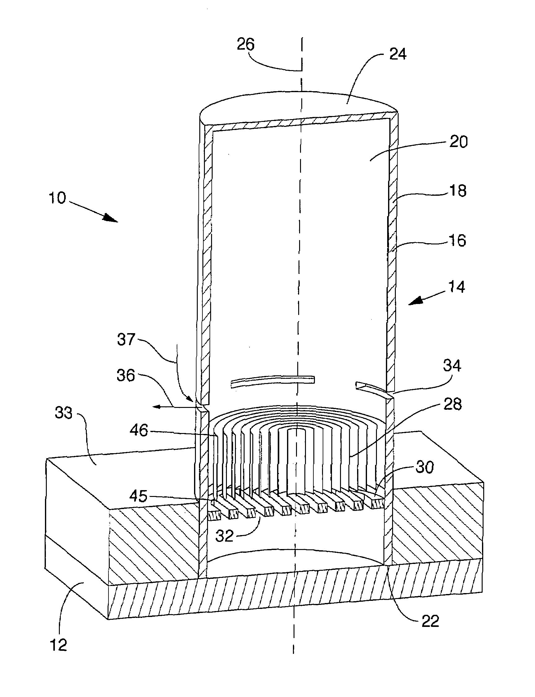
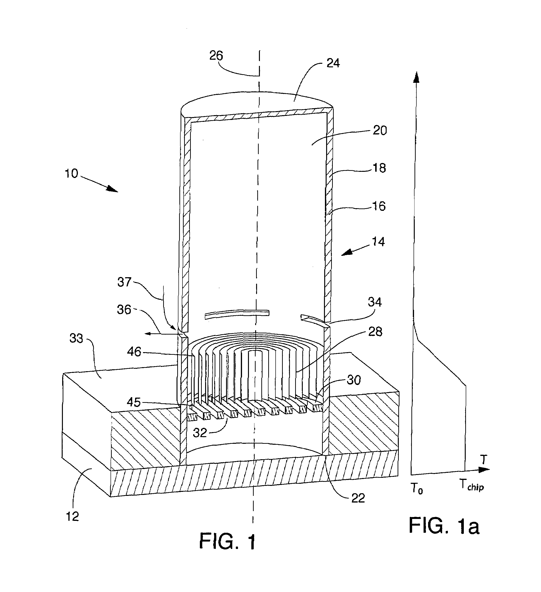
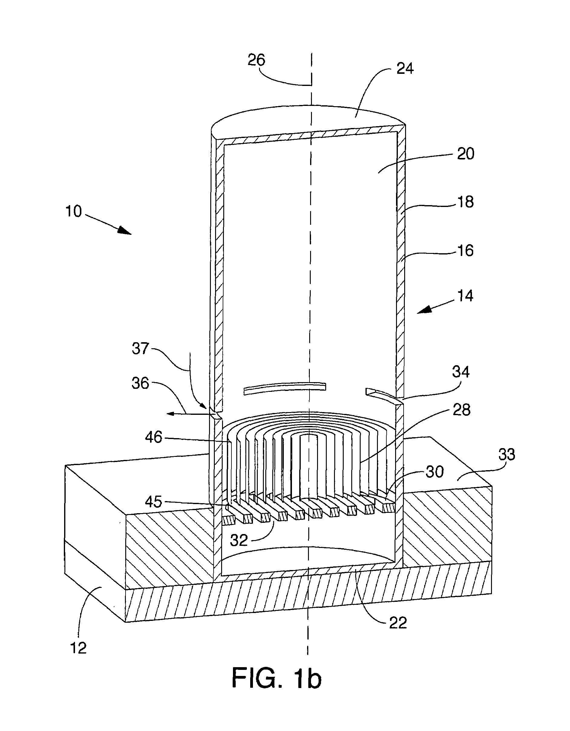
[0039]For the purposes of promoting an understanding of the principles in accordance with the disclosure, reference will now be made to the embodiments illustrated in the drawings and specific language will be used to describe the same. It will nevertheless be understood that no limitation of the scope of the disclosure is thereby intended. Any alterations and further modifications of the inventive features illustrated herein, and any additional applications of the principles of the disclosure as illustrated herein, which would normally occur to one skilled in the relevant art and having possession of this disclosure, are to be considered within the scope of the disclosure claimed.

[0040]The publications and other reference materials referred to herein to describe the background of the disclosure, and to provide additional detail regarding its practice, are hereby incorporated by reference herein in their entireties, with the following exception: In the event that any portion of said...


PUM

PropertyMeasurementUnit
speedaaaaaaaaaa
movementaaaaaaaaaa
temperaturesaaaaaaaaaa

Abstract

A thermoacoustic cooling system for cooling an object such as a microelectronic chip. Heat produced by the object is transferred to a thermoacoustic engine. The thermoacoustic engine may include a resonator defining a chamber. A stack may be positioned in the chamber with one side of the stack adjacent to the heat source, and the opposite side of the stack adjacent to air in the chamber having a relatively cooler temperature. One or more orifices may be formed in the resonator such that the acoustic power generated by the thermoacoustic engine creates a synthetic jet to circulate air and move the air away from the object being cooled. Thus, the heat produced by the object is used to power the thermoacoustic engine to thereby remove heat from the object. The thermoacoustic engine may use no moving parts and may require no external power source other than the object being cooled.

Description

CROSS-REFERENCE TO RELATED APPLICATIONS[0001]This application claims the benefit of U.S. Provisional Application No. 60 / 457,619, filed Mar. 25, 2003, which is hereby incorporated by reference herein in its entirety, including but not limited to those portions that specifically appear hereinafter, the incorporation by reference being made with the following exception: In the event that any portion of the above-referenced provisional application is inconsistent with this application, this application supercedes said above-referenced provisional application.STATEMENT REGARDING FEDERALLY SPONSORED RESEARCH OR DEVELOPMENT[0002]Not Applicable.BACKGROUND[0003]1. The Field of the Invention[0004]The present disclosure relates generally to cooling devices, and more particularly, but not necessarily entirely, to cooling devices having thermoacoustic engines for producing synthetic jets.[0005]2. Description of Related Art[0006]It is beneficial to remove heat from certain objects or areas in a v...

Claims


Application Information

Patent Timeline
Patent Type & Authority Patents(United States)
IPC IPC(8): F25B9/00B21D53/02H05K7/20F03G7/00F25B9/14
CPCF03G7/002F25B9/145F02G2243/54Y10T29/4935F25B2309/1403F25B2309/1407F25B2309/1416F25B2309/003
Inventor SMITH, BARTON L.
Owner UTAH STATE UNIVERSITY
Why Eureka
Try Eureka