Circulatory support system

a support system and circulatory tube technology, applied in the direction of heart stimulators, prostheses, therapy, etc., can solve the problems of reducing the usefulness of conventional bypass systems, requiring considerable set up time and continual management, and reducing the use of conventional bypass systems. , to achieve the effect of facilitating the pumping function of the right side of the hear

Inactive Publication Date: 2007-09-04
UNITED STATES SURGICAL CORP
View PDF105 Cites 79 Cited by
  • Summary
  • Abstract
  • Description
  • Claims
  • Application Information

AI Technical Summary

Benefits of technology

[0009]The support system is particularly contemplated for left heart bypass while the right heart functions to direct blood to the lungs. It is envisioned that the right heart may be slowed or even stopped while the support system is utilized for left heart bypass.
[0010]A method for providing at least partial bypass of the heart to supplement the pumping function of the heart to thereby enable the surgeon to perform various surgical procedures thereon is also disclosed. The method includes the steps of providing a circulatory assist system having a portable extracorporeal axial flow pump with a pump housing and inlet and outlet ports, a rotating pumping member disposed in the pump housing and inlet and outlet cannulated tubes respectively connected to the inlet and outlet ports of the pump housing, accessing the patient's left ventricle of the heart with the inlet cannulated tube, accessing the aorta with the outlet cannulated tube, actuating the rotating pumping member to draw oxygenated blood from the left ventricle of the heart through the lumen of the inlet cannulated tube and into the inlet port of the pump housing whereby the pumping member imparts mechanical energy to the oxygenated blood passing through the pump housing and directs the oxygenated blood through the outlet port and through the lumen of the outlet cannulated tube to be transferred by the aorta to the systemic arteries, and permitting blood returning through the systemic veins to the right atrium to be directed through the right ventricle to the patient's lungs for oxygenation and subsequent pulmonary circulation. The left ventricle may be accessed through the heart wall, mitral valve or aortic valve. In an alternate embodiment, a second circulatory assist system may be utilized to facilitate the pumping function of the right side of the heart.

Problems solved by technology

Although the aforedescribed cardiopulmonary bypass systems have been generally effective for their intended purposes, these systems are subject to certain disadvantages which detract from their usefulness.
In particular, conventional bypass systems are relatively complicated and expensive to manufacture, expose the blood to a high surface area of foreign materials which may damage the blood, require full anticoagulation and cooling of the heart, and require considerable set up time and continual management by a skilled technician.
These systems also require mechanical oxygenation of the blood which can have adverse affects on the patient.
The Mortensen '656 system, however, is also a relatively complex device including several pumps and an oxygenator and, consequently, requires attendance of skilled technicians for set-up and operation.

Method used


Image

  • Circulatory support system
  • Circulatory support system
  • Circulatory support system

Examples


Embodiment Construction

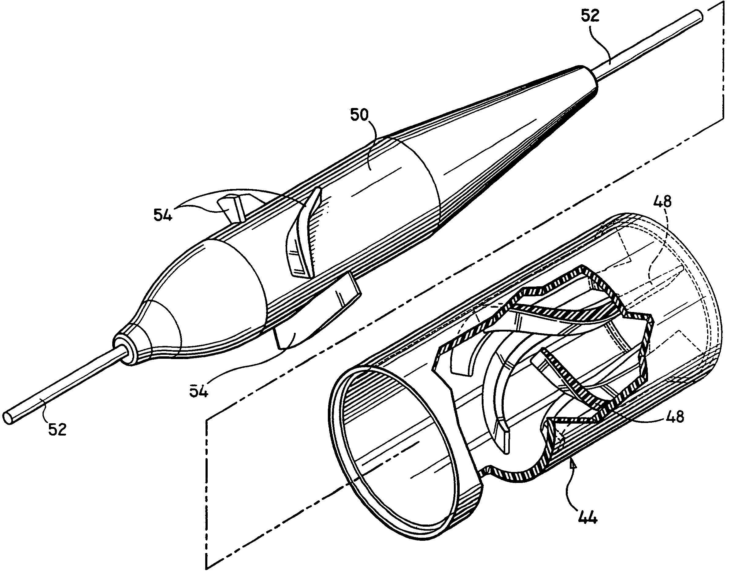
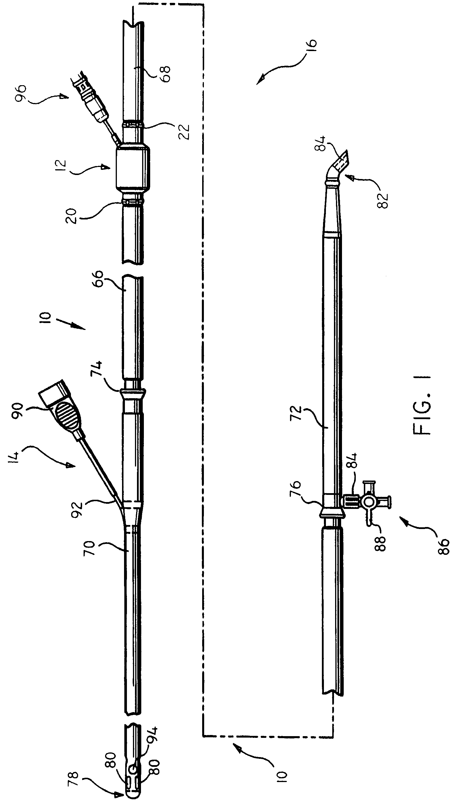
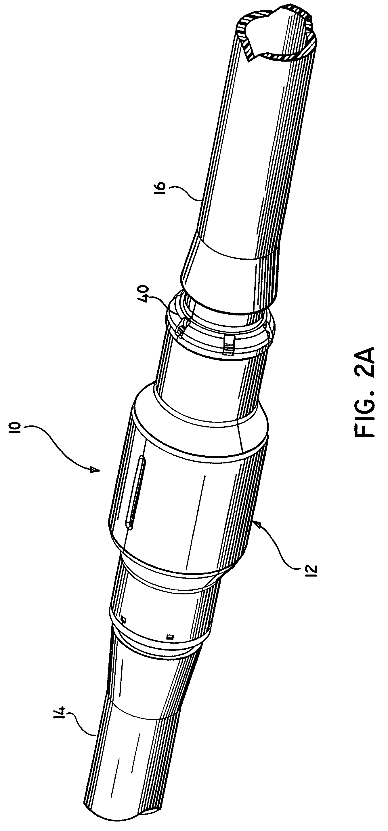
[0043]Referring now in detail to the drawings where like reference numerals identify similar or like components throughout the several views, FIG. 1 illustrates a preferred embodiment of the circulatory support system in accordance with the principles of the present disclosure. Particular features of support system 10 are also disclosed in U.S. Provisional Application Nos. 60 / 028,070, 60 / 026,656 and 60 / 026,657, each filed Oct. 4, 1996, and each entitled CIRCULATORY SUPPORT SYSTEM, the contents of each being incorporated herein by reference.

[0044]Circulatory support or bypass system 10 is contemplated to supplement or totally replace the pumping function of the heart during cardiac surgery and / or during temporary periods of heart failure. The system 10 can also be used during medical emergencies such as trauma, heart attack or heart failure. Circulatory support system 10 is particularly contemplated for patients in need of partial bypass of the left side of the heart while oxygenatio...


PUM


Abstract

A method for providing at least partial bypass of the heart to supplement the pumping function of the heart to thereby enable the surgeon to perform various surgical procedures thereon includes providing a circulatory assist system having a portable extracorporeal axial flow pump with a pump housing, a rotating pumping member disposed in the pump housing and inlet and outlet cannulated tubes respectively connected to inlet and outlet ports of the pump housing, accessing the patient's left atrium of the heart with the inlet cannulated tube, accessing the aorta with the outlet cannulated tube, actuating the rotating pumping member to draw oxygenated blood from the left atrium of the heart through the lumen of the inlet cannulated tube and into the inlet port of the pump housing whereby the pumping member imparts mechanical energy to the oxygenated blood passing through the pump housing and directs the oxygenated blood through the outlet port and through the lumen of the outlet cannulated tube to be transferred by the aorta to the systemic arteries and permitting the right side of the heart to function whereby oxygen-depleted blood returning through the systemic veins to the right atrium is directed through the right ventricle to the patient's lungs for oxygenation and subsequent pulmonary circulation.

Description

CROSS REFERENCE TO RELATED APPLICATIONS[0001]This application is a Continuation of U.S. patent application Ser. No. 09 / 328,248, filed on Jun. 8, 1999 now U.S. Pat. No. 6,716,189, which is a divisional application of U.S. patent application Ser. No. 08 / 943,504, filed Oct. 3,1997 now U.S. Pat. No. 5,965,089, which claims priority to U.S. Provisional Patent Application 60 / 028,070 filed on Oct. 4, 1996, U.S. Provisional Patent Application 60 / 026,656 filed on Oct. 4, 1996, and U.S. Provisional Patent Application 60 / 026,657 filed on Oct. 4, 1996, the disclosures of which are hereby incorporated by reference herein.BACKGROUND[0002]1. Technical Field[0003]The present disclosure relates generally to circulatory support systems, and, more particularly, to a circulatory support system to provide partial or total bypass of the heart. The present disclosure is further directed to an axial flow pump and a portable microprocessor-based controller each being adapted for use in the circulatory suppo...

Claims


Application Information

Patent Timeline
Patent Type & Authority Patents(United States)
IPC IPC(8): A61M37/00A61M1/36A61N1/362A61M1/00A61M5/00A61M1/10A61M39/28
CPCA61M1/101A61M1/3653A61M1/3626A61M1/3639A61M1/3666A61M39/281A61M1/3667A61M1/3656A61M1/3659A61M60/237A61M60/806A61M60/117
Inventor JARVIK, ROBERTALESI, DANIEL E.KLINGER, JOHN F.GEISTE, ROBERT J.DAY, STEVEN R.PAYEA, KEITHHAMMERQUIST, KENNETH G.STERN, STEVEN J.KACZYNSKI, FRANCIS X.HOWANSKY, MARKCASHIN, DEBORAH M.
Owner UNITED STATES SURGICAL CORP
Why Eureka
Try Eureka