Light emitting semiconductor device

a technology of light-emitting semiconductors and semiconductor devices, which is applied in the direction of semiconductor devices, electrical devices, nanotechnology, etc., can solve the problems of dominated light extraction efficiency of conventional light-emitting semiconductor devices, serious suppression of led light extraction efficiency,

Inactive Publication Date: 2007-09-04
ARIMA COMP
View PDF9 Cites 1280 Cited by
  • Summary
  • Abstract
  • Description
  • Claims
  • Application Information

AI Technical Summary

Problems solved by technology

Such a wave guiding effect will seriously suppress the light extraction efficiency of LED and is related to the planar technology for the LED structure growth from vapor phase.
However, such a design is disadvantageous for that a small number of structural defects existing in the mentioned layer sequence will seriously damage the light extraction efficiency of LED, and the wavelength of light generated by the QW is fixed so that a white light is unable to be generated therethrough.
Based on the above, it is apparent that the light extraction efficiency of a conventional light emitting semiconductor device is dominated and limited by the planar waveguide effect resulting from the planar technology for the light emitting semiconductor device and by the electrons current leakage in the active layer thereof.

Method used


Image

  • Light emitting semiconductor device
  • Light emitting semiconductor device
  • Light emitting semiconductor device

Examples


Embodiment Construction

[0060]The present invention will now be described more specifically with reference to the following embodiments. It is to be noted that the following descriptions of preferred embodiments of this invention are presented herein for purpose of illustration and description only; it is not intended to be exhaustive or to be limited to the precise form disclosed.

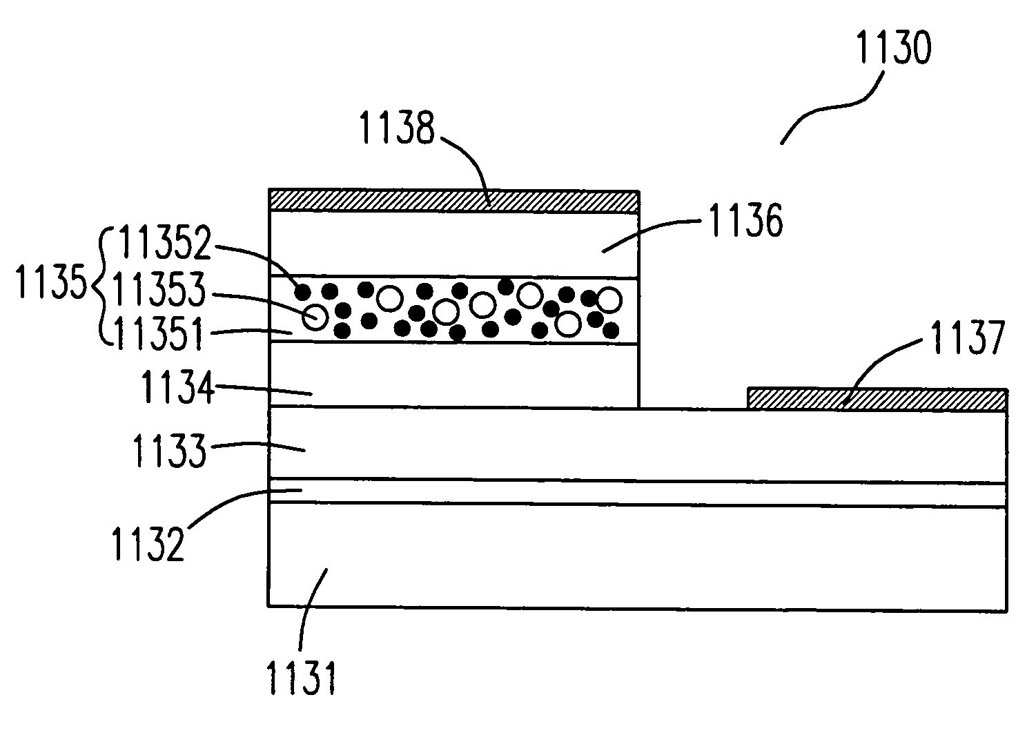
[0061]Please refer to FIG. 3, which schematically shows a general structure of the nano-particle buffer layer (NPBL) of the present invention. The NPBL 30 consists of a host layer 301 and a plurality of nano-particles 302, in which the host layer 301 is a doped or an undoped crystalline semiconductor material and the nano-particles 302 are crystalline, polycrystalline or amorphous particles. Moreover, the nano-particles 302 are made silicon oxides, silicon nitrides, aluminum oxides, gallium oxides or boron nitrides, e.g. SiO2, Si3N4, Al2O3, Ga2O3 and BN, respectively.

[0062]Please refer to FIG. 4, which schematically shows a NPBL ...


PUM


Abstract

A novel NPBL and ANPL light emitting semiconductor device and a method for fabricating the same are provided. In the present invention, plural nano-particles are applied in the active layer of the light emitting semiconductor device, so that the leakage current thereof is reduced. In addition, the provided light emitting semiconductor device fabricated via a planar technology process is microscopically planar, but not planar at micro- and nano-scale. Hence the parasitic wave guiding effect, which suppresses the light extraction efficiency of the light emitting semiconductor device, is destroyed thereby.

Description

FIELD OF THE INVENTION[0001]The present invention relates to a light emitting semiconductor device, in particular to a light emitting semiconductor device with a high efficiency.BACKGROUND OF THE INVENTION[0002]The light emitting diode (LED) is a fundamental component for electronic lighting technology. While a voltage is applied between the two electrode terminals of LED, which induces an electric current to pass through a p-n junction thereof, the LED will emit lights.[0003]The LED is advantageous for its long duty life, fast responding, high reliability, high electro-optic transforming efficiency and low consumption of electricity. Moreover, the miniaturization of the LED makes it suitable for mass production and makes it meet the requirements and trends for the technical development.[0004]LEDs emitting red, green, blue, infrared and ultraviolet lights have been marketed since early days, while the fabrication for the LED which emits visible lights is increasingly improved presen...

Claims


Application Information

Patent Timeline
Patent Type & Authority Patents(United States)
IPC IPC(8): H01L29/06H01L33/22
CPCH01L33/22Y10S977/773Y10S977/759Y10S977/76Y10S977/761
Inventor LEE, STEPHENSHRETER, YURY GEORGIEVICHREBANE, YURY TOOMASOVICHGORBUNOV, RUSLAN IVANOVICH
Owner ARIMA COMP
Why Eureka
Try Eureka