Head position control method, head position control device, and disk device

a control device and head position technology, applied in the direction of maintaining head carrier alignment, recording information storage, instruments, etc., can solve the problems of control system instability, unknown frequency, and inability to know the frequency in advance, and achieve high-quality follow-up control

Active Publication Date: 2007-09-04
KK TOSHIBA
View PDF14 Cites 18 Cited by
  • Summary
  • Abstract
  • Description
  • Claims
  • Application Information

AI Technical Summary

Benefits of technology

[0033]In the present invention, an accurate external vibration frequency, which is integral-compensated, can be estimated, since the external vibration frequency is estimated from a signal based on the position error according to an adaptive rule, and a highly accurate follow up control can be performed for a wide range of external vibration frequencies, since the constant of the compensator is corrected using this estimated external vibration frequency. In this way, the operation of the compensator can always be maintained at an optimum according to the value of the estimated external vibration frequency, and follow up control for a wide range of external vibration frequencies becomes possible by correcting the constant of the compensator.

Problems solved by technology

One factor that interrupts this positioning is eccentricity, which is caused by the center of the servo signals disposed concentrically on the disk that is different from the rotation center of the motor.
The second factor that interrupts this positioning is vibration, which is applied to the disk device from the outside.
The external vibration to be applied, however, is unknown at the point of designing the control system, so it is impossible to know the frequency in advance.
If this adjustment is not appropriate, the control system becomes unstable.
However if the disk device is used in the above-mentioned mobile environment, the range of the unknown disturbance frequency changes depending on the operating conditions, and cannot be easily estimated.
In the case of the adaptive control of a disturbance in prior art, the frequency range that can be followed up is limited, so in the above-mentioned operation environment, an adjusted gain and phase may be inappropriate, and may make the control system unstable.
The level of disturbance cannot be specified either, which makes the control system unstable, and may amplify errors or may even diverge errors.

Method used


Image

  • Head position control method, head position control device, and disk device
  • Head position control method, head position control device, and disk device
  • Head position control method, head position control device, and disk device

Examples


first embodiment

of Positioning Control System

[0093]FIG. 6 is a block diagram depicting the first embodiment of the positioning control system (servo control system) of the present invention, FIG. 7 is a block diagram depicting a variant form of FIG. 6, FIG. 8 is a block diagram depicting the disturbance suppression compensator in FIG. 6 and FIG. 7, FIG. 9 shows the configuration of the table for disturbance suppression compensation in FIG. 6 to FIG. 8, FIG. 10 shows another configuration of the table for disturbance suppression compensation in FIG. 6 to FIG. 8, and FIG. 11 are graphs depicting the F values stored in the tables in FIG. 9 and FIG. 10.

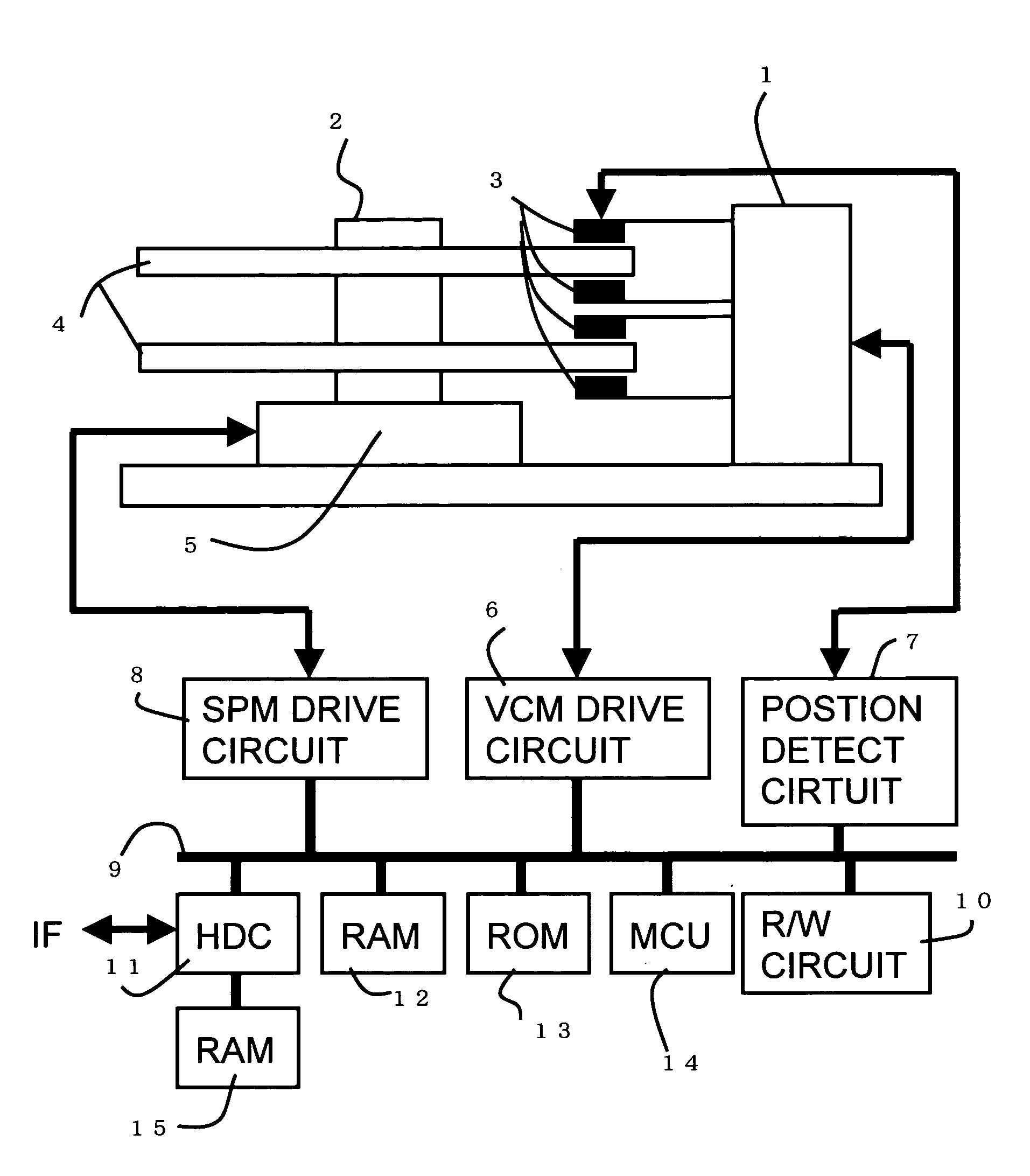
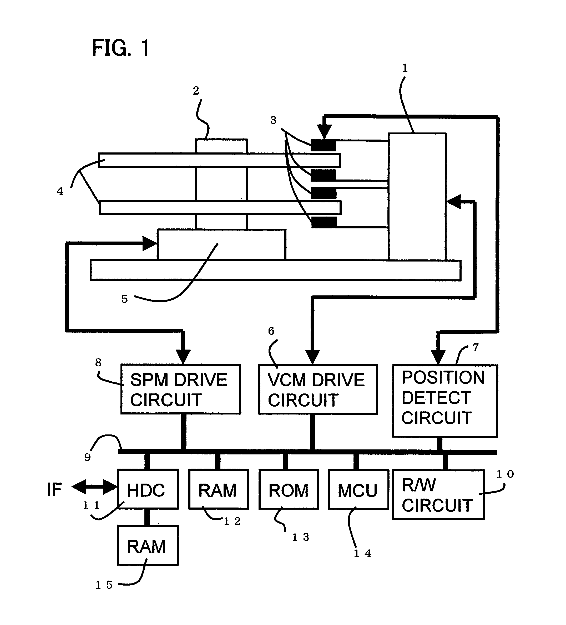
[0094]FIG. 6 is a block diagram depicting the computing of the servo control system executed by the MCU 14. In other words, the computing block 20 computes the position error ‘e’ between the target position ‘r’ and the current position ‘y’, the control block (Cn) 21 performs control-computing, calculates the control amount Un, and drives the VCM 1 (the h...

second embodiment

of Positioning Control System

[0172]FIG. 14 is a block diagram depicting the second embodiment of the positioning control system (servo control system) of the present embodiment, FIG. 15 shows block diagrams depicting the variant form of FIG. 14, FIG. 16 and FIG. 17 are diagrams depicting the calculation processing of the control system in FIG. 14 and FIG. 15, and FIG. 18 is a flow chart depicting the calculation processing of the servo control system in FIG. 14 and FIG. 15.

[0173]FIG. 14 is a block diagram depicting the computing of the servo control system executed by the MCU 14 in FIG. 1. In FIG. 14, composing elements the same as those in FIG. 6 are denoted with the same reference symbols. In other words, the position error ‘e’ between the target position ‘r’ and the current position ‘y’ is computed by the computing block 20, the control block (Cn) 21 performs control computation, calculates the control amount Un, and drives VCM 1 (and the head 3) which are the plant 22. For the p...

third embodiment

of Positioning Control System

[0190]FIG. 19 is a block diagram according to the third embodiment of the position control system (servo control system) of the present invention, and FIG. 20 is graphs depicting the embodiment in FIG. 19. The embodiment in FIG. 19 has a configuration for decreasing the data capacity of the compensation table 25. In other words, in the embodiments in FIG. 8 to FIG. 10, the table 25 holds the values G and F for all the estimated angular frequencies ω. In the case of the present embodiment, the same disturbance suppression compensation is performed with decreasing the data G and F in the table 25.

[0191]In FIG. 19, composing element the same as FIG. 8 are denoted with the same reference symbols. In other words, just like FIG. 8, the ω estimation section 24 comprises a computing block 24-1 for computing the second term (Ka·x1[k] . . . ) of the ω adaptive formula in Expression (20), a delay block 24-2 for delaying the estimated ω[k] by one sample, and an addi...


PUM

PropertyMeasurementUnit
frequencyaaaaaaaaaa
frequencyaaaaaaaaaa
frequencyaaaaaaaaaa

Abstract

A position control device corrects the displacement of the head by disturbance applied to the disk device by the control system. An adaptive control to an unknown disturbance frequency is performed. The frequency estimation block for estimating the external vibration frequency from a signal that is based on the position error according to the adaptive rule, and a correction table for sequentially correcting the constants of the compensator using this external vibration frequency, are provided. Since the constants of the compensator are sequentially corrected according to the estimated angular frequency, highly accurate follow up control to an external vibration frequency in a wide range becomes possible.

Description

CROSS-REFERENCE TO RELATED APPLICATIONS[0001]This application is based upon and claims the benefit of priority from the prior Japanese Patent Application No. 2005-187029, filed on Jun. 27, 2005, the entire contents of which are incorporated herein by reference.BACKGROUND OF THE INVENTION[0002]1. Field of the Invention[0003]The present invention relates to a head position control method for a disk device for suppressing the displacement of the head by disturbance and the disk device, and more particularly to a head position control method for suppressing the displacement of the head by external vibration and the disk device.[0004]2. Description of the Related Art[0005]In the case of a disk device, which reads and writes data on a rotating storage medium (e.g. disk medium) by a head, the head is positioned on a desired track of the storage medium and data is read from / written to the track by the head. For such a disk device, such as a magnetic disk device or optical disk device, it is...

Claims


Application Information

Patent Timeline
Patent Type & Authority Patents(United States)
IPC IPC(8): G11B5/596
CPCG11B5/5582G11B5/59688G11B7/08505G11B21/085G11B5/59627G11B7/0941G11B7/0946G11B11/10563G11B5/596G11B21/08G11B21/10G11B21/02
Inventor TAKAISHI, KAZUHIKO
Owner KK TOSHIBA
Why Eureka
Try Eureka