
Digital broadcast receiving device and digital broadcast receiving method

a digital broadcast and receiving device technology, applied in the field of digital broadcast receiving apparatus, can solve the problem of not being able to watch or listen to a desired channel program, and achieve the effect of convenient selection and receiving

Active Publication Date: 2007-09-04
FUJITSU GENERAL LTD
View PDF7 Cites 5 Cited by
  • Summary
  • Abstract
  • Description
  • Claims
  • Application Information

AI Technical Summary

Benefits of technology

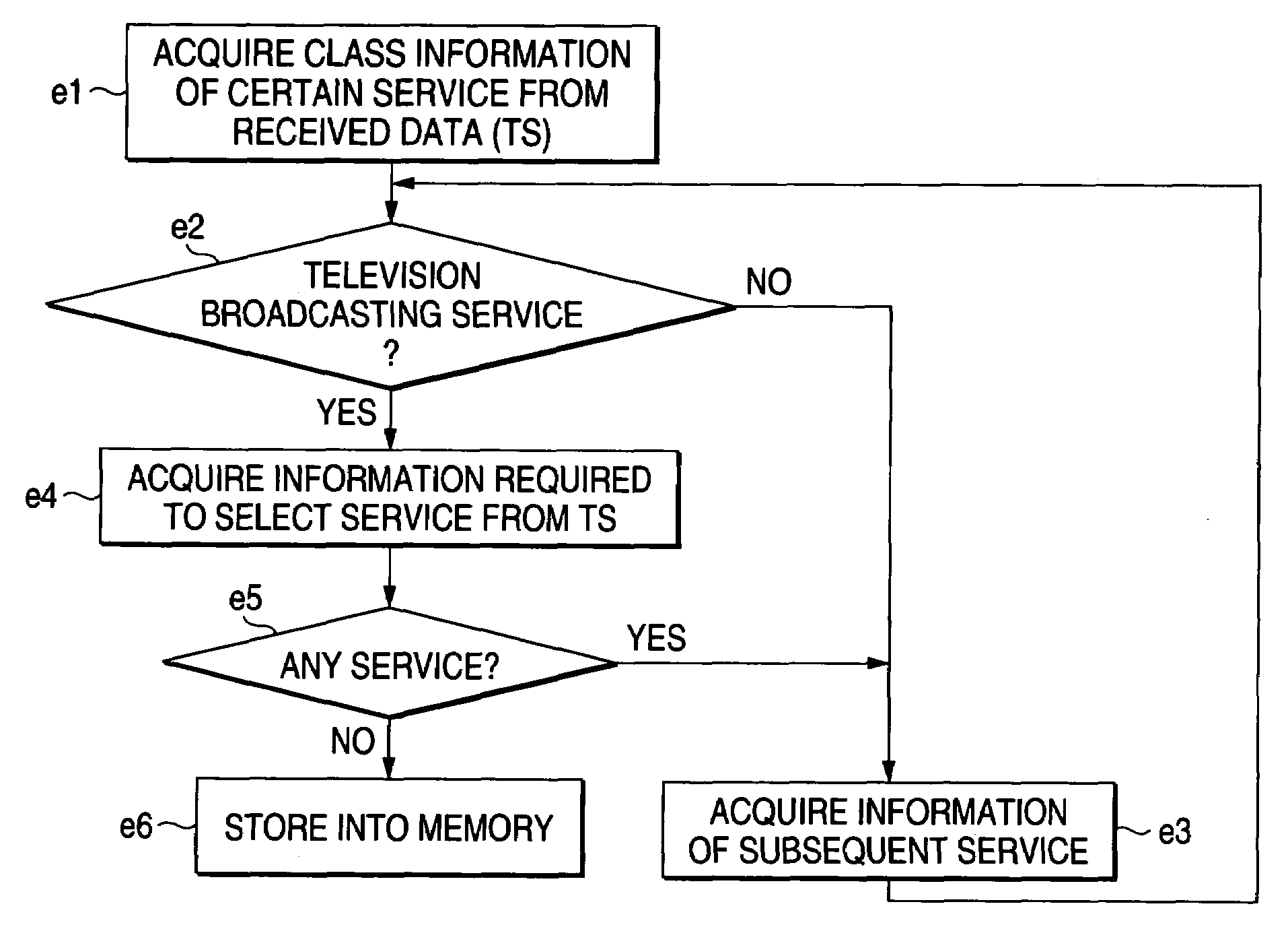
[0015]The tuner can achieve an automatic preset function of automatically repeating the storing operation in the memory for a plurality of different carrier frequencies received at present. In this way, the tuner scans the carrier frequency in order while changing it, receives the digital broadcast signal through the plurality of channels at a receivable carrier frequency or a carrier frequency at which receiving field strength is a preset value or greater, and stores the service information in the memory. Thus, SI can be preset in the memory all over the band of receivable carrier frequencies of the tuner, whereby the storing operation is facilitated without the operator needing to set the carrier frequency. The operator can easily select a program stored in the memory, and receive and view the program.
[0022]The temporary service information may be a temporary new when a sudden accident or disaster occurs, for example, in which the broadcast time or clock is irregular. The temporary service information does not exist after the broadcasting is ended in several minutes or hours, and may not be necessarily preset and stored in the memory. Accordingly, the temporary service information is preferably kept from being stored in the memory through an operation by operation input unit such as a pushbutton to improve the operability. Thus, it is possible to customize the service information to be preset in the memory according to the user's preference, with more excellent usability.
[0024]The service information is deleted from the memory, after the service preset in the memory is not broadcast. Accordingly, if the temporary service information is deleted from the memory, the user is easy to search the desired service information, and there is no fear that the not broadcast service information is displayed to make the operability worse. In this manner, since the service having the irregular broadcast time is preset in the memory after the temporary service, there is no time for broadcasting when that service information is selected at the next time, whereby there is no fear that an extra work is taken when the desired service information is searched.
[0027]In this manner, the service selection unit selects the service information stored in the memory. Thereby, the video for the selected service is displayed on a two-dimensional display plane of the display unit and the sound is output to the speaker of acoustic output unit by controlling at least one of the tuner and the decoding unit. Thus, when receiving the digital broadcast signal for a plurality of channels at one carrier frequency, the desired service information is easily selected and received.

Problems solved by technology

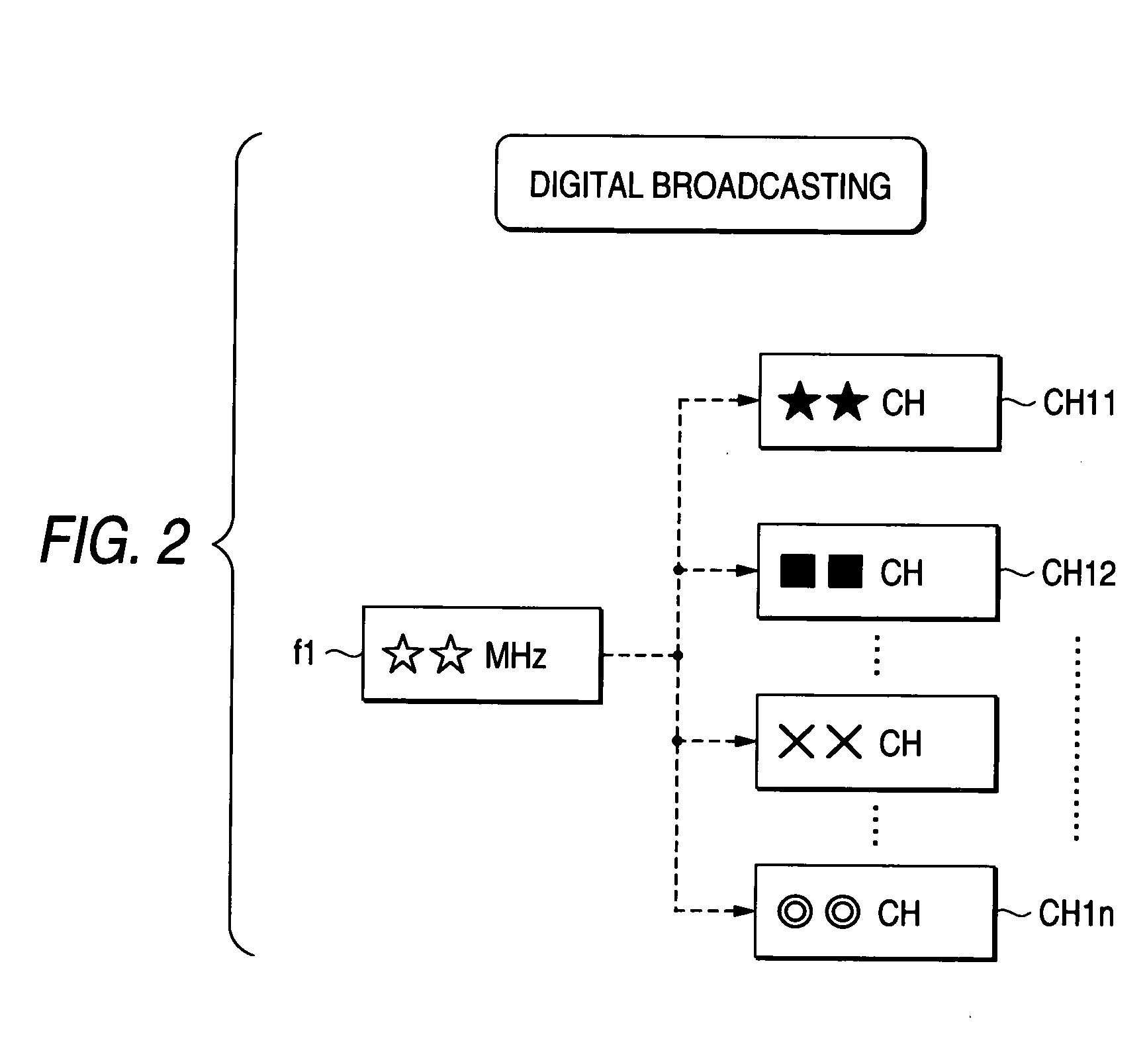
In such prior technique, since a digital broadcast signal involves a plurality of channels included in one carrier frequency, one cannot watch or listen to a desired channel program by selecting it, even though the channel is preset for the carrier frequency.

Method used


Image

  • Digital broadcast receiving device and digital broadcast receiving method
  • Digital broadcast receiving device and digital broadcast receiving method
  • Digital broadcast receiving device and digital broadcast receiving method

Examples


Embodiment Construction

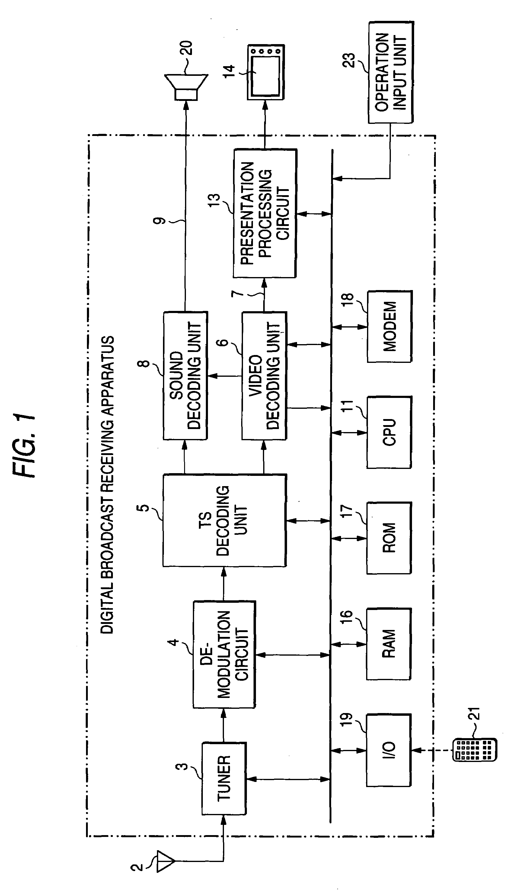
[0042]FIG. 1 is a block diagram showing the overall configuration of a digital broadcast receiving apparatus 1 according to one embodiment of the invention. A modulated carrier wave of a terrestrial broadcasting or satellite broadcasting received at an antenna 2 is tuned and received by a tuner 3, and demodulated by a demodulation circuit 4 to obtain a digital broadcast signal. This digital broadcast signal is supplied to Transport Stream (abbreviated as TS) decoding unit 5 to produce a TS. The TS is supplied to video decoding unit 6 to produce video data in a line 7 and is supplied to sound decoding unit 8 to produce the sound data in a line 9. A processing circuit 11 constituted by a microcomputer is connected via a bus 12 to the tuner 3, the demodulation circuit 4, the TS decoding unit 5, the video decoding unit 6, and the video decoding unit 8. The processing circuit 11 is further connected to a presentation processing circuit 13 for calculating the video data. A video signal fr...


PUM


Abstract

A tuner receives service information SI for each of a plurality of channels included in a digital broadcasting signal at one carrier frequency. A service information extraction unit extracts and stores the received service information preset into a memory. The operator selects the service information stored in the memory and acquires a program. The tuner may have a function of automatically scanning the carrier frequency all over the receivable frequency bands and store it. The temporary service information having irregular broadcast time is stored in the memory through an operation of an operation input unit. When the temporary service information is not broadcast, such temporary service information is deleted from the memory.

Description

[0001]The present disclosure relates to the subject matter contained in Japanese Patent Application No. 2002-277858 filed on Sep. 24, 2002, which is incorporated herein by reference in its entirety.BACKGROUND OF THE INVENTION[0002]1. Field of the Invention[0003]The present invention relates to a digital broadcast receiving apparatus for receiving a digital broadcast signal such as terrestrial broadcasting or satellite broadcasting.[0004]2. Description of the Related Art[0005]In a typical prior technique, service information regarding channels is stored in a unit of channel in the memory, with one channel CH corresponding to a certain carrier frequency, as shown in FIG. 14. By selecting the carrier frequency in a preset form of channel, the channel is determined. Thereby, one can watch or listen to a program on television broadcasting or radio broadcasting through a desired channel.[0006]In such prior technique, since a digital broadcast signal involves a plurality of channels includ...

Claims


Application Information

Patent Timeline
Patent Type & Authority Patents(United States)
IPC IPC(8): H04H1/00H04B7/00H05K11/00H03J1/00H04B1/16H04H20/00H04H20/28H04H60/07H04H60/72H04N5/44H04N5/50H04N7/025H04N7/03H04N7/035H04N7/08H04N7/081
CPCH03J1/0008H04H20/28H04H60/07H04H60/44H04H60/72H04N5/50H04N7/16H04N21/235H04N21/4335H04N21/4345H04N21/435H04N21/4383H04N21/84H04H60/73H04N5/4401H04N21/485H04N21/426
Inventor NAKAMURA, HIDEKI
Owner FUJITSU GENERAL LTD
Learn More