System and method for engine-controlled case splitting within multiple-engine based verification framework

a verification framework and engine-controlled case technology, applied in the field of integrated circuit design verification, can solve the problems of inefficiency in functional verification, inability to generate infinite tests, and inability to accurately verify the functionality of all components, and achieve the effect of reducing the number of tests

Active Publication Date: 2007-09-04
GOOGLE LLC
View PDF2 Cites 11 Cited by
  • Summary
  • Abstract
  • Description
  • Claims
  • Application Information

AI Technical Summary

Problems solved by technology

Indeed, the verification of advanced integrated circuits, such as microprocessors with multiprocessing capability, is now estimated to consume more time, labor, and other resources than the actual design of the device.
Unfortunately, generating a seemingly infinite number of tests is an inefficient and unreliable method of verifying the functionality of all components in the integrated circuit.
In the early days of microprocessor development, inefficiencies in functional verification were tolerated because the size of the test space (measured, for example, by the number of states the microprocessor may assume) was sufficiently small.
The increasing number of functional units in microprocessors is significant from a verification perspective because interaction between functional units can no longer be ignored or only loosely verified by conventional verification methodologies.
Because of the many possible applications and uses of modern integrated circuits, integrated circuit designers cannot predict and test every possible real-world configuration in which the integrated circuit may be employed.
The conventional approach to functional verification, in which increased complexity in a device is verified by simply increasing the number of tests that are simulated, is rapidly becoming infeasible.
In addition, because the input to a simulator in a conventional verification process is simply a large number of deterministic tests or randomly generated tests, the output of the simulation must be painstakingly evaluated to determine whether a particular simulation was successful in testing the intended functionality of the device.

Method used


Image

  • System and method for engine-controlled case splitting within multiple-engine based verification framework
  • System and method for engine-controlled case splitting within multiple-engine based verification framework
  • System and method for engine-controlled case splitting within multiple-engine based verification framework

Examples


Embodiment Construction

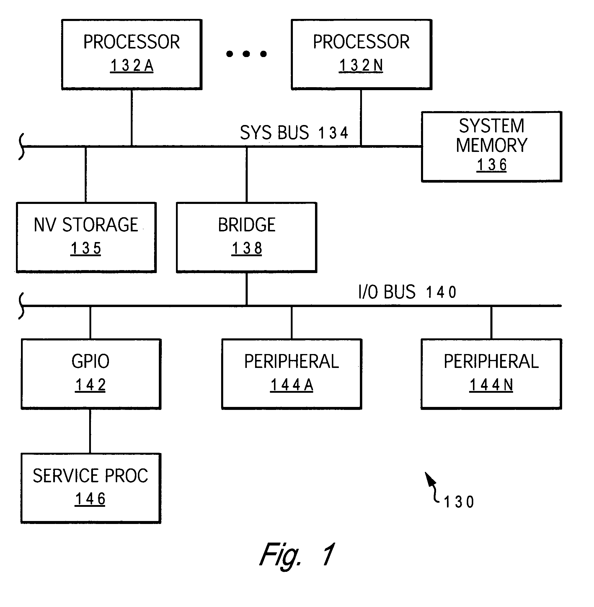
[0017]With reference to the figures and in particular with reference to FIG. 1, there is depicted a block diagram illustrating an exemplary data processing system 130 in which a preferred embodiment of the present invention may be implemented.

[0018]As depicted, data processing system 130 includes a set of main processors 132a through 132n (generically or collectively referred to as processor(s) 132) that are coupled to a system bus 134. A system memory 136 is accessible to each processor 132 via system bus 134. System memory 136 is typically implemented with a volatile storage medium such as an array of dynamic random access memory (DRAM) devices. The depicted architecture of data processing system 130 is frequently referred to as a symmetric multiprocessor (SMP) system because each processor 132 has substantially equal access to system memory 136.

[0019]As depicted, non-volatile (NV) storage 135 (e.g., a hard disk drive or read-only memory) is coupled to system bus 134. Also, a bus ...


PUM


Abstract

A system and method for implementing a verification system. Included is a first set of verification engines for attempting to solve a verification problem. At least one of the first set of verification engines divides the verification problem into a set of partitions and passes at least one of the set of partitions to a second set of verification engines. Each one of the set of partitions may be passed to a distinctly separate verification engine. A system framework is configured to communicate with an application program and further configured to instantiate at least one verification engine in a user-defined sequence. Included within at least one of the first set of verification engines is a means for communicating verification information to the second set of verification engines.

Description

BACKGROUND OF THE INVENTION[0001]1. Technical Field[0002]The present invention generally relates to the field of integrated circuit design verification and more particularly to a system and method for managing integrated circuit design verification utilizing modular design verification engines and a verification framework that employ a common interface to facilitate the exchange of verification information and design flows.[0003]2. Description of the Related Art[0004]As the complexity of microprocessors and other sophisticated integrated circuits has increased over the years, the resources devoted to integrated circuit design verification has accounted for an increasingly large percentage of the total resources required to develop and manufacture an integrated circuit. Indeed, the verification of advanced integrated circuits, such as microprocessors with multiprocessing capability, is now estimated to consume more time, labor, and other resources than the actual design of the device...

Claims


Application Information

Patent Timeline
Patent Type & Authority Patents(United States)
IPC IPC(8): G06F17/50
CPCG06F17/5022G06F30/33
Inventor BAUMGARTNER, JASON RAYMONDKANZELMAN, ROBERT LOWELLMONY, HARIPARUTHI, VIRESH
Owner GOOGLE LLC
Why Eureka
Try Eureka