Synchronization of seismic data acquisition systems

a seismic data and acquisition system technology, applied in the field of seismic survey equipment, can solve the problems of affecting the image quality of subsurface geologic layers, the accuracy of the timing accuracy of the recorded data, and the need for very accurate time-based time-based time-based data, so as to facilitate the improvement of synchronization, less transmission delay, and tight statistical distribution of transmission times

Active Publication Date: 2007-09-11
INOVA SYST CORP
View PDF25 Cites 74 Cited by
  • Summary
  • Abstract
  • Description
  • Claims
  • Application Information

AI Technical Summary

Benefits of technology

[0019]The invention includes a method of time-stamping data by a higher-precision clock before transmission of data to a device containing another clock further distributed in the network there by facilitating improvement in synchronization by shared reliance on the accuracy of the high-precision clock.
[0020]According to one aspect of the invention, the seismic network may include a high-speed backbone connecting lower speed branches to a central point wherein the backbone has less transmission delay and a tighter statistical distribution of transmission times enabling better synchronization of the clocks connected to the backbone.
[0021]All aspects of the invention may contribute to the better synchronization of seismic sources and / or of the recording of seismic data by the receivers, enabling improved seismic imaging of the earth's subsurface.

Problems solved by technology

One of the key difficulties of a widely distributed seismic data acquisition system is that the transducers which measure the seismic vibrations of the earth must be very accurately timed, relative to a system-wide master clock.
Less accurate timing can result in signal degradation in the various stages of processing to which the measured seismic reflections are subsequently subjected.
The ultimate goal, to image the subsurface geologic layers, may be severely compromised by errors in timing accuracy of the recorded data.
Difficulties in guaranteeing accurate timing arise due to the wide geographic dispersal of the seismic sensor arrays, often over varying and difficult terrain.
The distances and obstacles separating the seismic receivers and sources make the synchronization of these seismic survey system elements very challenging.

Method used


Image

  • Synchronization of seismic data acquisition systems
  • Synchronization of seismic data acquisition systems
  • Synchronization of seismic data acquisition systems

Examples


Embodiment Construction

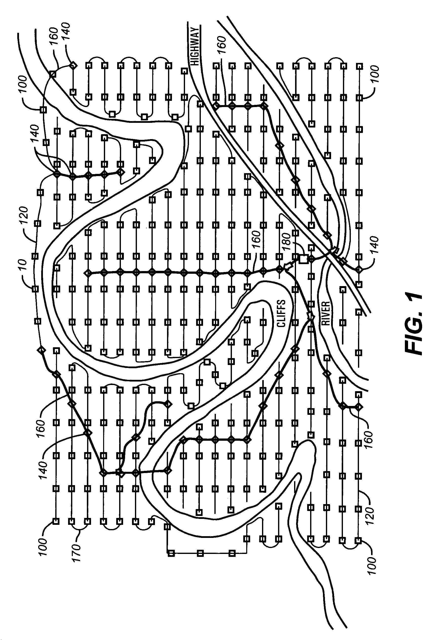
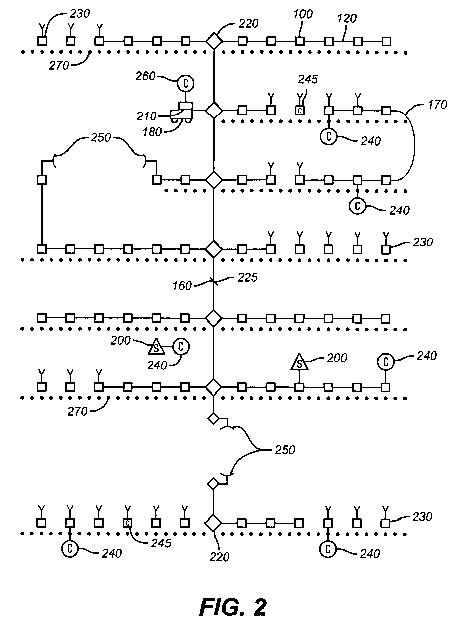
[0029]For reference, a typical seismic survey grid is shown schematically by FIG. 1 to include a large number of remote acquisition modules (RAMs) 100 having orderly connections along receiver lines 120 to respective line tap units 140. Line tap units (LTUs) 140 connect receiver lines 120 to base lines 160. The base lines 160 connect ultimately to the central recording unit (CRU) 180. Jumpers 170 connect ends of receiver lines 120 to form loops. RAMs 100 perform functions of collecting seismic sensor array signals, digitizing these signals if they are not already digitized within the arrays, and transmitting the data toward the CRU 180. Also the RAMs 100 receive communications originated by the CRU 180 and by more remote RAMs 100 and relaying this information to adjacent RAMs 100 or LTUs 140.

[0030]Seismic sensors are connected to the RAMs 100 and may be of one or more types of transducers such as geophones or hydrophones. Sensor arrays may range from single sensors to multiple senso...


PUM


Abstract

A network distributed seismic data acquisition system comprises seismic receivers connected to remote acquisition modules, receiver lines, line tap units, base lines, a central recording system and a seismic source event generation unit synchronized to a master clock. One or more high precision clocks is added to the network to correct for timing uncertainty associated with propagation of commands through the network. Seismic receivers and seismic sources are thereby synchronized with greater accuracy than otherwise possible. Timing errors that interfere with the processing of the seismic recordings are greatly reduced, thus enabling an improvement in subsurface geologic imaging.

Description

CROSS-REFERENCE TO RELATED APPLICATIONS[0001]This application claims the benefit of U.S. Provisional Application No. 60 / 416,070 filed Oct. 4, 2002.STATEMENT REGARDING FEDERALLY SPONSORED RESEARCH OR DEVELOPMENT[0002]Not applicableFIELD OF THE INVENTION[0003]The present invention relates to seismic survey equipment. In particular, the invention relates to equipment assembly combinations and the synchronization of a widely distributed network of seismic receivers and seismic sources using both a wired and a wireless medium.BACKGROUND OF THE INVENTION[0004]In principle, a seismic survey represents an analysis of the earth's geologic structure as indicated by seismic reflections from impedance discontinuities at lithologic interfaces. The analysis is influenced by seismic wave propagation velocities respective to the successively deeper geologic formations. A precisely-timed seismic source event, such as the ignition of buried explosives in a shallow borehole or a controlled mechanicall...

Claims


Application Information

Patent Timeline
Patent Type & Authority Patents(United States)
IPC IPC(8): G01V1/22G01V1/24G01V1/26
CPCG01V1/22G01V1/26
Inventor CHAMBERLAIN, DONALD G.HEIDEBRECHT, NORMAN DAVID
Owner INOVA SYST CORP
Why Eureka
Try Eureka