Method for dynamic diagnosis of an exhaust gas analyzer probe

a technology dynamic diagnosis, which is applied in the direction of machines/engines, electrical control, instruments, etc., can solve the problems of faulty analysis of exhaust gas analyzer, aging exhaust gas analyzer probe, and exchange, so as to reduce the risk of a faulty diagnosis, reduce the risk of aging, and increase the discriminatory power

Inactive Publication Date: 2007-09-18
ROBERT BOSCH GMBH
View PDF9 Cites 12 Cited by
  • Summary
  • Abstract
  • Description
  • Claims
  • Application Information

AI Technical Summary

Benefits of technology

[0007]This objective is achieved by implementing the dynamic diagnosis of the exhaust gas analyzer probe with a closed-loop control, the deviation of the measuring signal (lambda-actual) of a slowing exhaust gas analyzer probe from the setpoint value (lambda-setpoint) being amplified by the intervention of the controller, and the dynamic diagnosis being carried out on the basis of this amplified deviation. This heavily emphasizes the dynamic deviations of a slowing exhaust gas analyzer probe so that they can be detected in a reliable manner. In contrast, stochastically occurring faults cancel each other on average and can be reliably differentiated from the systematic fault of a slowing exhaust gas analyzer probe. The method thus increases both the discriminatory power between exhaust gas analyzer probes having different dynamic responses and also the robustness of the system with respect to stochastically occurring faults. This minimizes the risk of a faulty diagnosis. The setpoint value is, in particular, the nominal setpoint value, i.e., a setpoint value for an ideal probe and ideal path dynamics.
[0008]In a preferred specific embodiment of the present invention, the control parameters of the controller are selected such that the control loop begins to oscillate with an exhaust gas analyzer probe that begins to slow to below a predefined limit value. This may be achieved, in particular, in a closed loop with a fast controller. The oscillation leads to a clear and detectable inflation of the deviation between the setpoint value (lambda-setpoint) and the measuring signal (lambda-actual). No defined jump in the exhaust-gas composition, for instance in the transition of the internal combustion engine to overrun operation with fuel cutoff, is required to induce the oscillation since even undefined changes in the exhaust-gas composition induce the system to oscillate when a slow exhaust gas analyzer probe is present, and this is easily detectable.

Problems solved by technology

However, in reality both methods supply a fuzzy result because of the controller reaction and the stochastics due to the evaluation of a single signal.
This may not only have the result that an aged exhaust gas analyzer probe is not detected in time but also that a still intact exhaust gas analyzer probe is deemed faulty and is exchanged.

Method used


Image

  • Method for dynamic diagnosis of an exhaust gas analyzer probe
  • Method for dynamic diagnosis of an exhaust gas analyzer probe
  • Method for dynamic diagnosis of an exhaust gas analyzer probe

Examples


Embodiment Construction

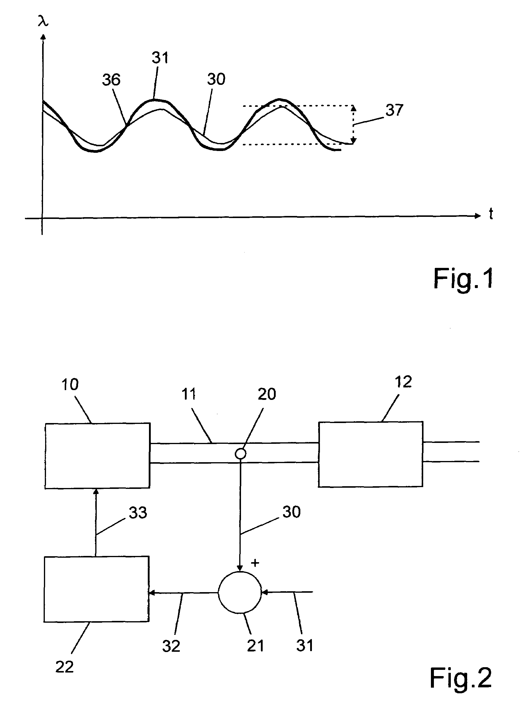
[0016]FIG. 1 illustrates the time characteristic of measuring signal (lambda-actual) 30 of an aged exhaust gas analyzer probe 20 compared to the predefined setpoint value (lambda-setpoint) 31 in a high-frequency excitation according to a diagnosis method of the related art. Gradient 36 of measuring signal (lambda-actual) 30 is analyzed in the region of the reversal point of the oscillation and / or amplitude 37. A slowing exhaust gas analyzer probe 20 leads to a reduced gradient 36 of the measuring signal (lambda-actual) 30 and / or to a reduced amplitude 37 compared to predefined setpoint value (lambda-setpoint) 31. In contrast, a new exhaust gas analyzer probe 20 largely follows the setpoint value (lambda-setpoint) 31. The dynamic response of an exhaust gas analyzer probe 20 is thus able to be determined on the basis of the deviation of gradient 36 and / or amplitude 20. However, the methods supply stable information only when the control loop of exhaust gas analyzer probe 20 has no sig...


PUM


Abstract

A method for the dynamic diagnosis of an exhaust gas analyzer probe situated in an exhaust-gas system having at least one exhaust-gas catalytic converter, of an internal combustion engine, a measuring signal (lambda-actual) of the exhaust gas analyzer probe being compared to a setpoint value (lambda-setpoint) as a function of the operating state of the internal combustion engine, and the system deviation being supplied to a controller, which regulates the operating parameters of the internal combustion engine correspondingly, the dynamic diagnosis of the exhaust gas analyzer probe being implemented with a closed control loop, and the deviation from the setpoint value (lambda-setpoint) of the measuring signal (lambda-actual) of a slowing exhaust gas analyzer probe being amplified by the intervention of the controller and the dynamic diagnosis is implemented on the basis of this amplified deviation. The method allows a reliable diagnosis of the dynamic response of the exhaust gas analyzer probe with excellent differentiation with respect to stochastically occurring fault signals.

Description

FIELD OF THE INVENTION[0001]The present invention relates to a method for dynamic diagnosis of an exhaust-gas analyzer probe which is situated in an exhaust-gas system of an internal combustion engine having at least one exhaust-gas catalytic converter, a measuring signal (lambda-actual) of the exhaust gas analyzer probe being compared to a setpoint value (lambda-setpoint) as a function of the operating state of the internal combustion engine; the control difference is supplied to a controller which controls the operating parameters of the internal combustion engine accordingly.BACKGROUND INFORMATION[0002]The ageing of such an exhaust gas analyzer probe leads to a longer response time with respect to changes in the exhaust-gas composition, i.e., in the dynamic response of the exhaust gas analyzer probe. However, a rapid reaction of the entire control loop, and thus also of the exhaust gas analyzer probe, to changes in the exhaust-gas composition is a prerequisite for operating the i...

Claims


Application Information

Patent Timeline
Patent Type & Authority Patents(United States)
IPC IPC(8): G01M15/10
CPCF01N11/007F02D41/1439F02D41/1495F01N2560/02Y02T10/47Y02T10/40
Inventor SCHNAIBEL, EBERHARDWEHMEIER, KERSTEN
Owner ROBERT BOSCH GMBH
Why Eureka
Try Eureka