Method of lining a pipeline

a technology of pipelines and linings, applied in the direction of shaft linings, shaft equipment, mechanical equipment, etc., can solve the problems of pipeline deterioration, pipeline deterioration, holes, cracks, etc., and achieve the effect of preventing deterioration and preventing deterioration

Active Publication Date: 2007-09-18
WARREN ENVIRONMENTAL & COATING LLC
View PDF39 Cites 19 Cited by
  • Summary
  • Abstract
  • Description
  • Claims
  • Application Information

AI Technical Summary

Benefits of technology

[0012]In this regard, the present invention provides a method for installing a liner in a pipeline, such as an underground water pipeline. Installing such a liner enables a damaged pipeline to be repaired and salvaged and placed in a condition for normal use. In accordance with the method of the present invention, the interior surface of the pipeline to be repaired and salvaged is first prepared by removing excess debris and dirt. For example, water is preferably sprayed at up 30,000 psi to clean and prepare the interior surface of the pipe. Even higher pressures can be used, if necessary. The pipe is then cleared of the standing water by high-pressure air. Next, a first thermosetting resin having a light color pigment therein is applied to the interior surface of the pipeline. Then, a flexible lining hose is filled with a second thermosetting resin, which is preferably clear or translucent. The filled lining hose is then drawn through rollers to fully wet interior of the lining hose. The flexible lining hose is then inverted into the pipeline placing the interior wetted surface of the lining hose against the interior surface of the pipeline. The lining hose has a flexible non-permeable outer layer and an inner layer that is preferably made of felt material. Next, a calibration hose is introduced into the lining hose. Pressurized fluid is injected into the calibration hose to press the lining hose against the interior surface of the pipeline and substantially cure the second thermosetting resin. This curing step causes the lining hose to physically bond to the interior surface of the pipeline. Afterwards, the calibration hose is removed from inside of the lining hose. Laterals are identified and cleared using a robot with a camera thereon. The laterals are identified easily using the method of the present invention because the lateral location appears as a dark spot in the clear resin as contrasted to the light colored resin applied to the interior wall of the pipeline in the first resin application. The resulting composite structure includes a rigid lining hose firmly attached to the pipeline with a rugged, smooth and leak-free sealing inner surface of epoxy material which will be in communication with the flowing liquid in the pipe during normal use.
[0013]Therefore, it is an object of the present invention to provide a new and novel process for lining the interior surface of a pipeline to repair and salvage the pipe so that is can be used normally in a leak-free condition. It is another object of the invention to provide a structural lining process that effectively seals all cracks and faults in an existing pipeline. A further object of the invention is to provide a structural lining process that installs a sealing inner liner that is well suited to seal corner joints within a pipeline. A further object of the present invention is to provide a structural lining process that relatively inexpensive to carry out compared to prior art processes without sacrificing the integrity of the sealing and repair accomplished by the process of the present invention. Yet another object of the invention is to provide a method of installing a pipeline liner that improves the overall strength of the pipeline and enhances the ability of the installer to identify and clear lateral connections.

Problems solved by technology

Since these pipelines are installed underground, they are constantly subjected to numerous environmental pressured that cause the pipeline to deteriorate.
For example, the pipeline may deteriorate due to ordinary aging, corrosive action of the fluids being transported in the line, environmental conditions such as groundwater exposure, or other reasons.
Over time, all of the wear factors that impact on the pipeline result in holes, cracks, and other defects in the line that must be repaired in order to prevent fluid leakage problems.
In some instances, the concern is that foreign matter, which is initially part of the actual construction of the pipeline, may begin to flake off of the interior surfaces of the damaged pipeline and enter the fluid flow within the pipeline.
For example, ductile iron piping has a clay liner surface that upon failure may allow rust to enter the fluid flow.
Finally, the potential exists for the introduction of substances that flow from the surrounding underground environment into the pipeline or for the water that is being carried through the pipeline conduit to flow outwardly through the cracks leading to a loss of water pressure and other problems.
Given the millions of miles of installed pipeline in the United States alone, this solution would be prohibitively expensive.
Further, such pipelines are typically located beneath streets and right of ways where digging would create traffic flow problems and require extensive repaving of roadways as the replacement process was completed.
Although the above-described conventional methods may be somewhat effective in repairing pipelines, they still suffer from various problems.
For example, problems arise concerning the inversion of a felt liner because it is relatively delicate and tends to break or rip during the inversion process.
Also, pulling prior art liner tubes around corners is very difficult resulting in fractures in the sealing at such joints.
Also, the pipeline joints found at corners and periodically along the length of the pipeline forms voids that cannot be completely filled by the prior art methods.
Thus, the prior art methods can do nothing to improve the strength of the pipeline at its joints.
Another difficulty is that once a liner has been installed, the identification of lateral supply pipe branches are difficult to identify and clear.

Method used


Image

  • Method of lining a pipeline
  • Method of lining a pipeline
  • Method of lining a pipeline

Examples


Embodiment Construction

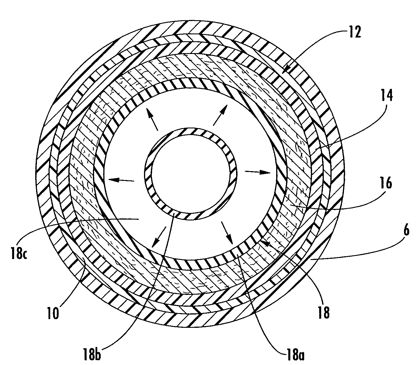
[0020]Now referring to the drawings, the method for repairing a pipeline in accordance with the teachings of the present invention is shown and generally illustrated in the figures. In summary, the process of the present invention is used to repair a damaged underground pipeline, such as a water line, so that it can used in the normal course without undesirable leaks. As can be understood, cracks and leaks in a fluid line is undesirable to the associated pressure drops and flow inefficiencies. Further, in a cracked pipeline, particles commonly break off from the inner surface of the pipeline thereby contaminating the fluid that flows through the pipeline.

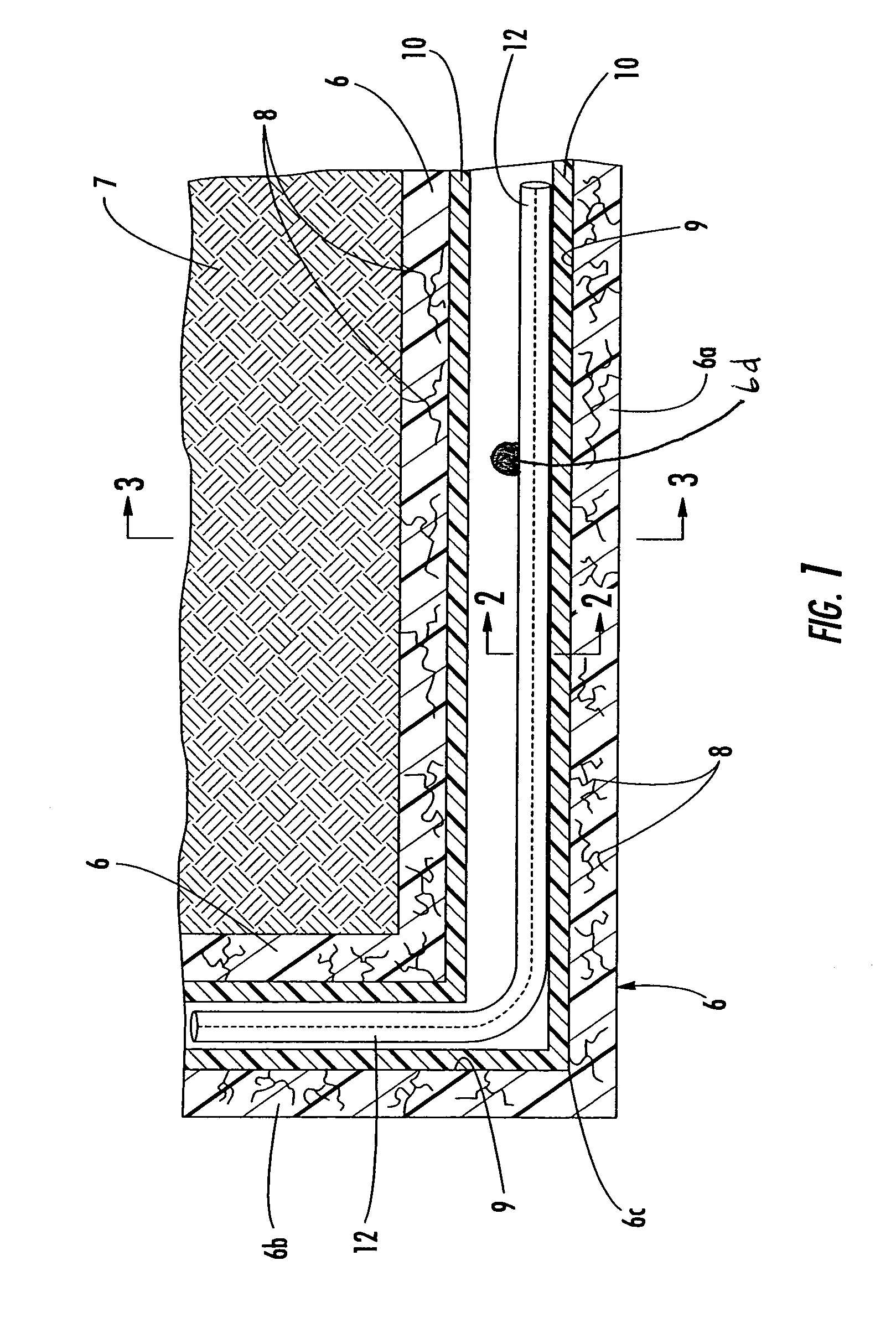
[0021]Referring first to FIG. 1, a side cross-section view of a typical pipeline installation is shown. The pipeline or host pipe 6 is installed in the ground 7 where a number of cracks 8 exist representing undesirable leaks. The pipeline 6 includes a horizontal section 6a and a vertical section 6b with a lateral supply branch 6d ex...


PUM


Abstract

The present invention is an improved method for installing a liner to repair a pipeline. The method involves placing a flexible lining hose that is coated with a thermosetting resin into the pipeline. A quick setting resin is also applied to the interior walls of the pipeline wherein the resin has a high contrast pigment agent therein in order to facilitate identification of and reopening of the various service laterals. A calibration hose is introduced into the lining hose and pressurized fluid is injected therein. The fluid presses the lining hose against the interior surface of the pipeline and cures the first and second thermosetting resins. The curing of the resins bonds the lining hose to the pipeline to form a rigid monolithic composite structure having high mechanical strength.

Description

BACKGROUND OF THE INVENTION[0001]The present invention relates generally to a method for repairing a pipeline, such as a sewer pipe, by installing a liner inside of the pipeline. More specifically, the present invention relates to a process wherein a curable resin system is applied to the inside walls of the pipeline in a two part process where a first resin is spun onto the pipeline wall and a second resin is coated onto a flexible fabric liner that is then installed into the pipeline.[0002]Throughout developed parts of the world, there are numerous pipeline conduits that run underground in order to provide utility services to businesses and residences. These utilities include water lines, sewer pipes, storm water drains, and the like. Since these pipelines are installed underground, they are constantly subjected to numerous environmental pressured that cause the pipeline to deteriorate. For example, the pipeline may deteriorate due to ordinary aging, corrosive action of the fluids...

Claims


Application Information

Patent Timeline
Patent Type & Authority Patents(United States)
IPC IPC(8): F16L55/16
CPCF16L55/165F16L55/1654
Inventor WARREN, DANIEL
Owner WARREN ENVIRONMENTAL & COATING LLC
Why Eureka
Try Eureka