
Illumination device and its use

a technology of a chromatic device and a beam intensity, which is applied in the field of chromatic devices, can solve the problems of poor efficiency in the utilization of beam intensity originally generated, and the approach of u.s. patent no. 4,862,299 is unsuitable for chromatic reasons, and achieves the effect of compact design

Inactive Publication Date: 2007-09-18
CARL ZEISS MICROSCOPY GMBH
View PDF15 Cites 5 Cited by
  • Summary
  • Abstract
  • Description
  • Claims
  • Application Information

AI Technical Summary

Benefits of technology

[0010]The variant with diaxial aspherical curvature can be used particularly advantageously for the homogenization in an intermediate plane of a wide-field microscope. Also in the case of multi-point scanning microscopes the homogeneous illumination of an intermediate image in front of the element which generates the point cloud (for example, a Nipkow disk) makes possible a uniform illumination of the sample with spatially essentially more uniform beam intensity. Also, the converting unit according to the invention makes possible the illumination of an objective pupil so that a particularly good (highly resolved) imaging is achieved since a homogeneously filled pupil permits the optical resolution to be fully exploited.
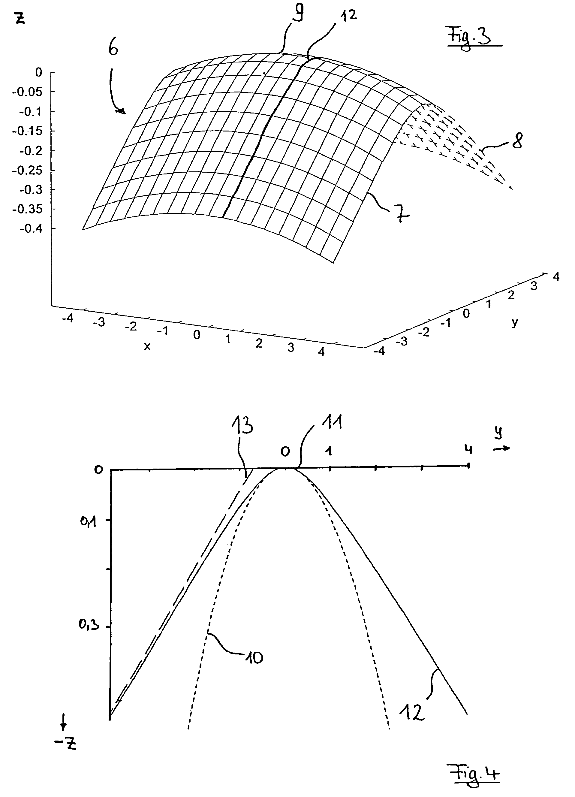
[0011]A form of embodiment which is particularly simple to manufacture is a mirror which is formed as a wedge and with a rounded top. Such a mirror can be produced in a simple manner from a cuboid and achieves a focal line with a homogeneous energy distribution.
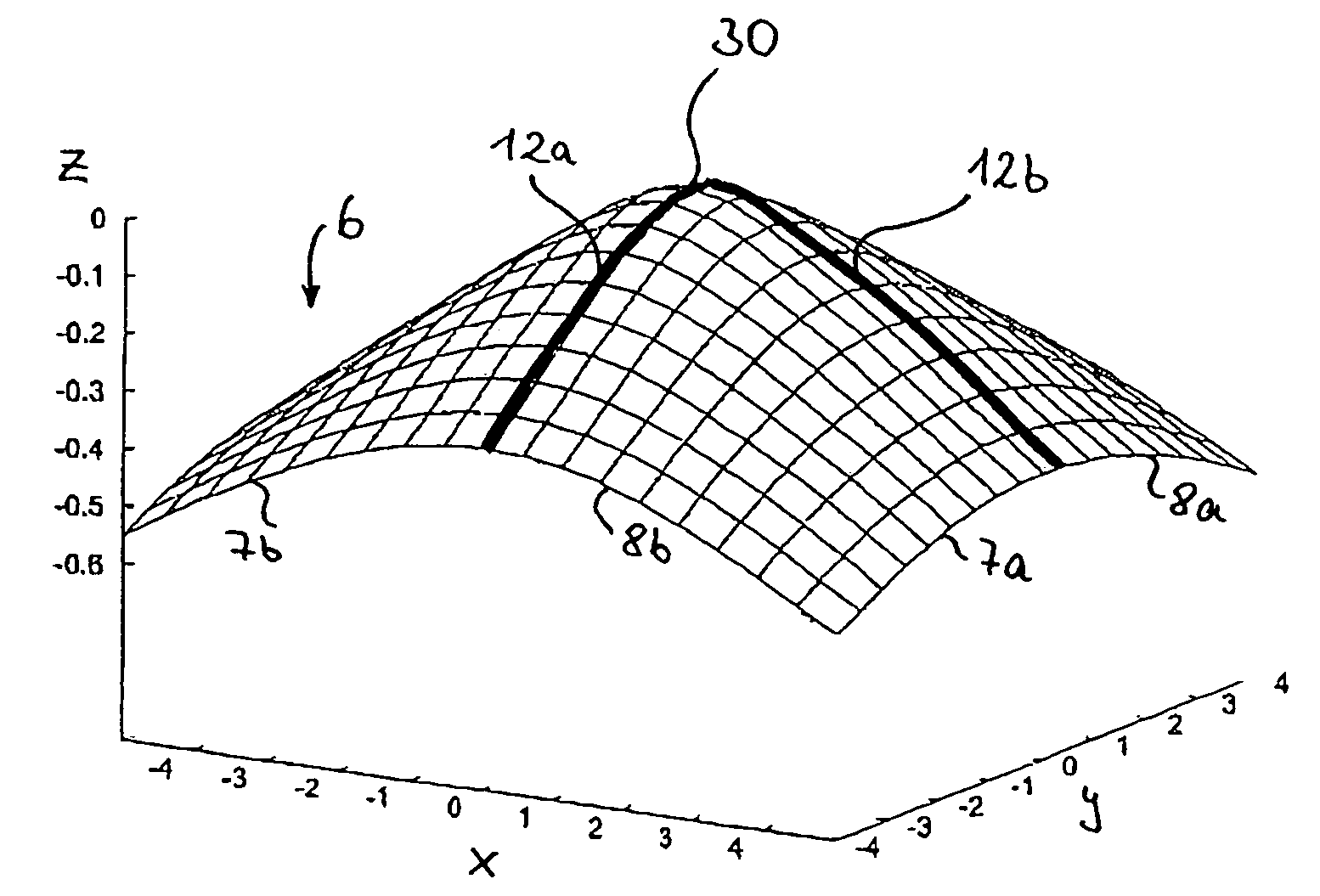
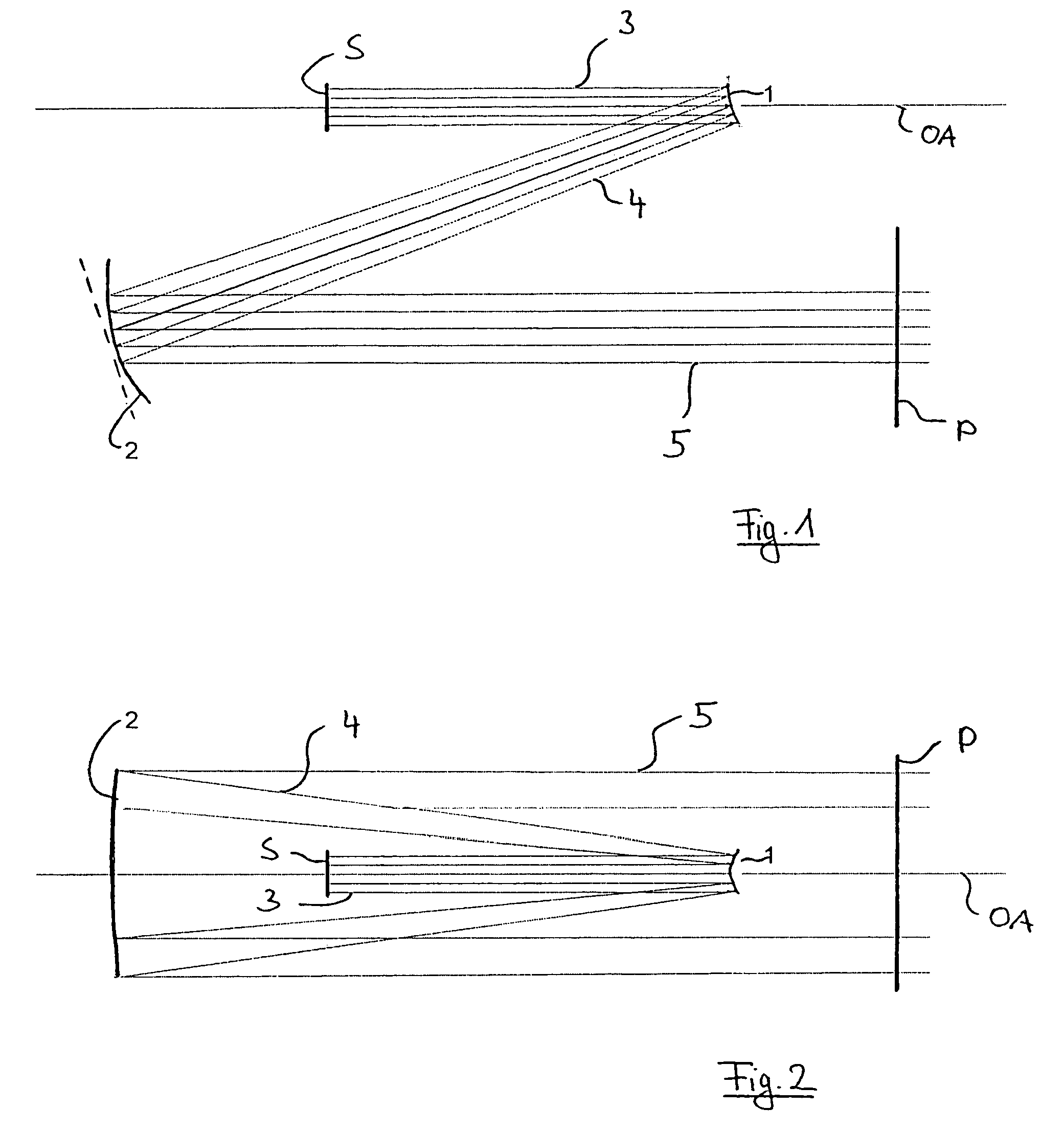
[0021]For the illumination of the aspherical mirror it is advantageous to set the axis of symmetry of the mirror at an angle between 4° and 20° to the axis of incidence of the original beam, which is profiled, for example, to be Gaussian-shaped, since then a compact design can be obtained. The collecting mirror disposed behind, which can be formed, for example, cylindrically or toroidally, collects the radiation energy redistributed by the aspherical surfaces and compensates wave aberrations accumulating during the propagation. If such wave aberrations play no role in simple cases, a spherical lens can be used instead of the collecting mirror.

Problems solved by technology

Unfortunately, this has poor efficiency with regard to the utilization of the beam intensity originally generated.
For application in laser scanning microscopy the approach of U.S. Pat. No. 4,862,299 is, however, unsuitable for chromatic reasons.

Method used


Image

  • Illumination device and its use
  • Illumination device and its use
  • Illumination device and its use

Examples


Embodiment Construction

[0033]FIGS. 1 and 2 show an illumination arrangement in which radiation from a radiation source S is re-formed with respect to its beam profile. FIG. 1 is a section in a (z, x)-plane. FIG. 2 is a section perpendicular thereto in a (z, y)-plane. The radiation source S transmits a beam which is profiled to be Gaussian-shaped in each sectional direction perpendicular to the direction of propagation. After the re-formation a beam is present in a profile plane P which illuminates essentially a rectangular field, where the intensity distribution is not Gaussian-shaped along the longitudinal field axis but rather chest-shaped.

[0034]For beam forming, an aspherical mirror 1 is used which expands the radiation. The expanded radiation is parallelized once more by means of a collecting mirror 2. The aspherical mirror 1 is struck by an original beam 3 from the radiation source S, said beam having said rotationally symmetric Gaussian-shaped beam profile. The aspherical mirror 1 is curved in the s...


PUM


Abstract

To provide an illumination beam (5) which is essentially homogeneous in cross-section, in particular for a laser scanning microscope (15), an illumination device is used which provides an original beam which is essentially rotationally symmetric in cross-section and is incident at a converting unit which then transmits the desired illumination beam (5) and which comprises, for this purpose, an aspherical, convex mirror (1) which is more strongly curved in the area of the point of incidence of the original beam (3) than in the areas removed from the point of incidence.

Description

BACKGROUND OF THE INVENTION[0001]1. Field of the Invention[0002]The invention relates to an illumination device which provides an illumination beam which is essentially homogeneous in at least one cross-sectional direction, in particular for a laser scanning microscope, where an original beam which is inhomogeneous in cross-section, in particular Gaussian-shaped, is conducted to a converting unit which transmits the illumination beam.[0003]2. Related Art[0004]In many applications an illumination beam expanded in the form of a line is used, for example, for barcode scanners or for laser scanning microscopes sampling in the form of a row. One possibility for obtaining such a beam in the form of a line consists of a fast redirection of the laser beam along a row so that indeed at each point in time only one point of the row is illuminated, but averaged over a certain period of time a row is illuminated. Another approach which is also used in the state of the art to generate illuminatio...

Claims


Application Information

Patent Timeline
IPC IPC(8): G02B5/10G02B21/06
CPCG02B27/0927G02B27/0977
Inventor GOELLES, MICHAELWOLLESCHENSKY, RALFGRAEFE, DIETERWALD, MATTHIAS
Owner CARL ZEISS MICROSCOPY GMBH
Learn More