Optoelectronic transmission and/or reception arrangement

a technology of optoelectronic transmission and reception arrangement, applied in the direction of optics, instruments, optical light guides, etc., can solve the problems of error in the transfer behavior of lasers, and achieve the effects of cost-effective production, high coupling efficiency, and cost-effectiveness

Active Publication Date: 2007-09-18
II VI DELAWARE INC
View PDF9 Cites 9 Cited by
  • Summary
  • Abstract
  • Description
  • Claims
  • Application Information

AI Technical Summary

Benefits of technology

[0027]The transmission and / or reception module is preferably formed as a surface-mountable component. The invention makes it possible to use an optoelectronic SMD component which is produced cost-effectively using customary production lines and does not have to have an integrated, optically imaging element. Through the use of a subassembly with an optical waveguide section and a coupling lens arranged at a defined distance with respect thereto, an optical coupling of such an SMD component to an optical waveguide to be coupled is nevertheless provided with high coupling efficiency and without the need for active adjustment in the Z direction.
[0028]The lens used may comprise a planar substrate, such as silicon, for example. For this case, mounting in the panel with subsequent singulation is possible, so that a particularly cost-effective solution is present. In this case, the plane rear side of the lens substrate, which does not have a light-shaping region, is fixed on a spacer or the end side of a ferrule. A connection between the lens and the spacer or the end side of the ferrule can correspondingly be produced in a simple manner, for instance by adhesive bonding.

Problems solved by technology

Thus, feedbacks at optical interfaces arranged in the beam path lead to errors in the transfer behavior of the laser.

Method used


Image

  • Optoelectronic transmission and/or reception arrangement
  • Optoelectronic transmission and/or reception arrangement
  • Optoelectronic transmission and/or reception arrangement

Examples


Embodiment Construction

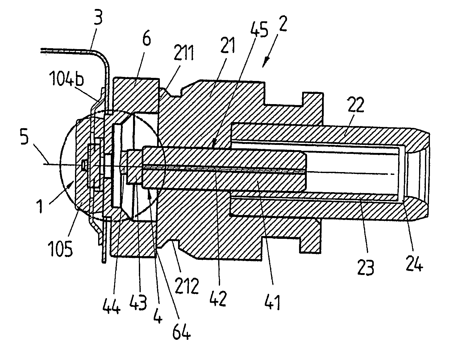
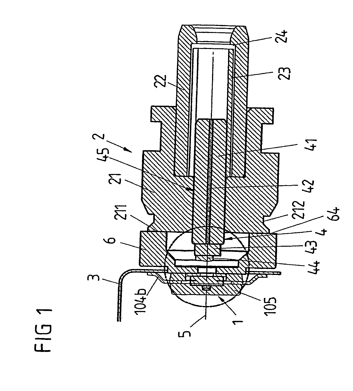
[0044]FIGS. 1 to 3, 5 and 6 show a first exemplary embodiment of an optoelectronic transmission and / or reception arrangement having a transmission and / or reception module 1 embodied as an SMD component and a plug interface 2 coupled to the transmission and / or reception module 1.

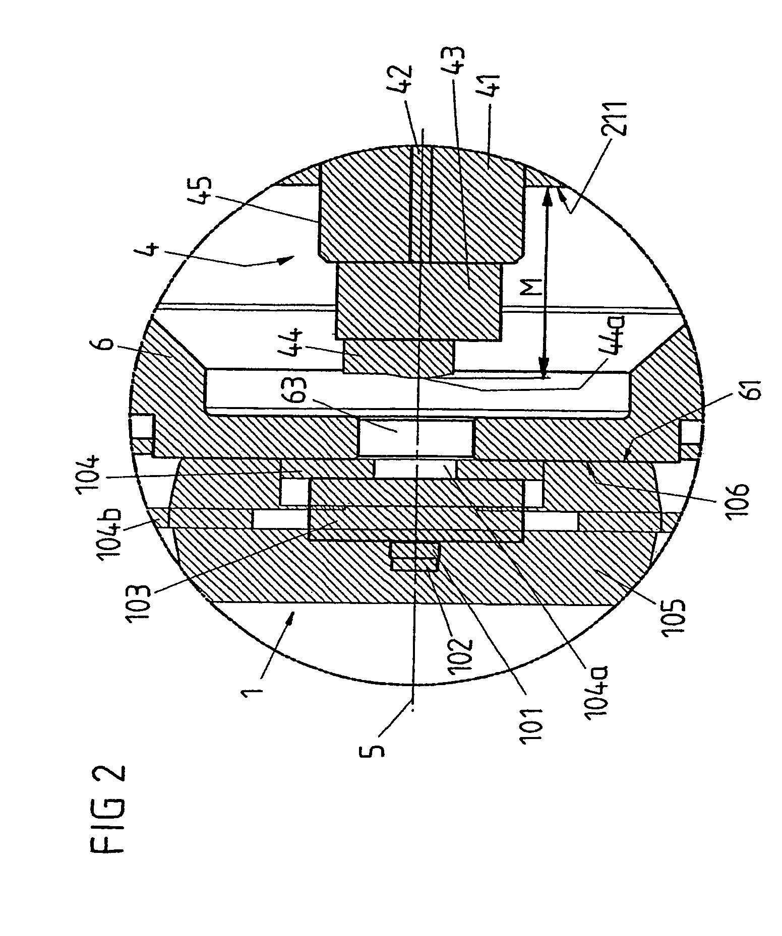
[0045]The SMD component 1 of FIG. 1 includes a vertically emitting laser 101, a monitor diode 102, a submount 103, a leadframe 104 and a plastic sheathing 105. In this case, the laser 101 is arranged with the active side downward (face-down mounting) on the submount 103, the submount being transparent to the transmission and / or reception wavelength. A gap that possibly exists between the laser 101 and the submount 103 is filled with an optically transparent medium in the optically active region.

[0046]The monitor diode 102 is arranged on the rear side of the laser 101 and detects a fraction of the radiation emitted by the laser diode 101 and serves for regulating the laser 101 in a manner known per se.

[0047]Th...


PUM


Abstract

The invention relates to an optoelectronic transmission and/or reception arrangement. The arrangement includes a transmission and/or reception module containing an optoelectronic transmission and/or reception component, and a plug interface for the coupling of an optical fiber thereto. An optical waveguide section is arranged in the plug interface, and at one of its ends is optically coupled to the transmission and/or reception component. At its other end, the optical waveguide section is configured to be coupled to an optical fiber. The arrangement may further include a lens for optical coupling of the light between the optical waveguide section and the transmission and/or reception component. The lens and the optical waveguide section, in one example, are formed as a prefabricated subassembly, in which the lens is fixedly arranged at a defined distance from one end face of the optical waveguide section.

Description

REFERENCE TO RELATED APPLICATIONS[0001]This application claims the benefit of the priority date of German application DE 103 29 988.2 filed on Jun. 27, 2003, the contents of which are herein incorporated by reference in their entirety.FIELD OF THE INVENTION[0002]The invention relates to an optoelectronic transmission and / or reception arrangement having a transmission and / or reception module and a plug interface. It relates in particular to the optical coupling of an optoelectronic surface-mountable component to a standard plug interface.BACKGROUND OF THE INVENTION[0003]DE 199 09 242 A1 discloses an optoelectronic module in which a leadframe with an optoelectronic transducer is positioned in a module housing and potted with a light-transmissive, moldable material. Light is coupled in or out via an optical fiber coupled to a connector of the module housing. The driver module or reception module for the optoelectronic transducer is also situated on the leadframe.[0004]DE 199 61 624 A1 ...

Claims


Application Information

Patent Timeline
Patent Type & Authority Patents(United States)
IPC IPC(8): G02B6/36G02B6/42
CPCG02B6/4206G02B6/421G02B6/4292
Inventor ALTHAUS, HANS-LUDWIGPLICKERT, VOLKERMELCHIOR, LUTZKILLER, THOMAS
Owner II VI DELAWARE INC
Why Eureka
Try Eureka