System and method for pulse welding

a pulse welding and pulse welding technology, applied in the field of pulse welding, can solve the problems of low deposition rate prone to burnout of thin workpiece materials, and high heat input of short-circuit welding techniques

Inactive Publication Date: 2007-09-18
LINCOLN GLOBAL INC
View PDF20 Cites 34 Cited by
  • Summary
  • Abstract
  • Description
  • Claims
  • Application Information

AI Technical Summary

Benefits of technology

[0007]A summary of one or more aspects of the invention is now presented in order to facilitate a basic understanding thereof, wherein this summary is not an extensive overview of the invention, and is intended neither to identify certain elements of the invention, nor to delineate the scope of the invention. Rather, the primary purpose of the summary is to present some concepts of the invention in a simplified form prior to the more detailed description that is presented hereinafter. The present invention relates to apparatus and methods for pulse welding in which the initiation of the molten metal transfer is controlled according to the amount of energy applied to the electrode. The invention may be employed to facilitate pulse welding in which the size (e.g., volume) of molten material is generally uniform at the beginning of the transfer pulse, such that the pulse waveform can be tailored to produce good transfer characteristics with little or no energy from the transfer pulse adding to the electrode heating. The initiation of the pulse based on applied energy, moreover, allows tailoring of the transfer pulse at or near the minimal energy to achieve repeatable non-short-circuit ball transfer without excessive pulse heating, wherein the pulse operates primarily to transfer the molten ball (e.g., to separate or detach the molten material from the electrode). Thus, during each welding cycle a selected constant amount of energy is applied to the wire for heating of the wire, wherein the welding power source or a controller associated therewith initiates the transfer pulse when a predetermined amount of energy has been applied independent of arc current and voltage fluctuations or other process variations. The applied energy can be correlated with the volume of molten material at the end of the electrode, so that the size of the transferred molten ball is essentially the same for each cycle. This predictable ball size, in turn, allows the transfer pulse size and shape to be tailored to properly detach the ball without stretching, without short-circuiting, and without the pulse energy contributing significantly to the electrode heating, by which a predictable volume of molten metal can be repeatably transferred in each welding cycle.

Problems solved by technology

This type of welding is prone to spatter that disrupts the weld pool and / or to cold lapping where there is not enough energy in the puddle for the filler material to fuse properly to the workpiece.
In addition, short-circuit welding techniques suffer from low deposition rates compared with pulse or spray welding.
This technique exhibits rather high heat input and is useful only over a limited range of welding positions.
Spray welding is also prone to burnthrough on thin workpiece materials.
However, the arc current also exerts a magnetic force on the molten weld pool on the workpiece, pushing the weld puddle downwardly away from the end of the electrode, wherein this downward force may push the molten metal outwardly and cause a puddle depression below the electrode.
This depression and the associated electromagnetic forces can cause extreme weld puddle agitation for high pulse current levels, especially when welding metals aluminum or other material having low specific gravity, leading to a poor weld bead appearance and excessive penetration of the metal into the workpiece.
This, of course, is a tradeoff, wherein a pulse that does not contain sufficient energy may lead to short circuit conditions and the associated spatter problems.
In particular, a relatively weak pulse may fail to fully separate the molten metal from the remainder of the electrode before the ball engages the weld puddle, causing a substantial amount of spatter.
However, if the energy in the current pulse is too great, severe puddle agitation occurs.
Such overcompensation to avoid short-circuit conditions, however, is not universally acceptable, particularly for more susceptible processes, such as very thin workpieces.
Non-optimal electrode current waveforms results in excessive spatter or an excessive arc length, wherein a long arc can lead to a contaminated weld and reduced overall welding travel speed.
With respect to variations in the size of the transferred material, if the molten ball is too small at the beginning of the transfer condition, the pulse current may cause the ball to be “stretched” or pulled as pinch forces attempt to detach the droplet, in which case the bottom of the molten ball can contact the weld puddle (short-circuit), resulting in spatter.
However, this situation is only achievable if the volume of the molten metal ball is repeatable and uniform for each welding cycle at the time the high current pulse is applied.
However, process variation is inevitable as conditions, materials, temperatures, etc. change over time or from one workpiece to the next.

Method used


Image

  • System and method for pulse welding
  • System and method for pulse welding
  • System and method for pulse welding

Examples


Embodiment Construction

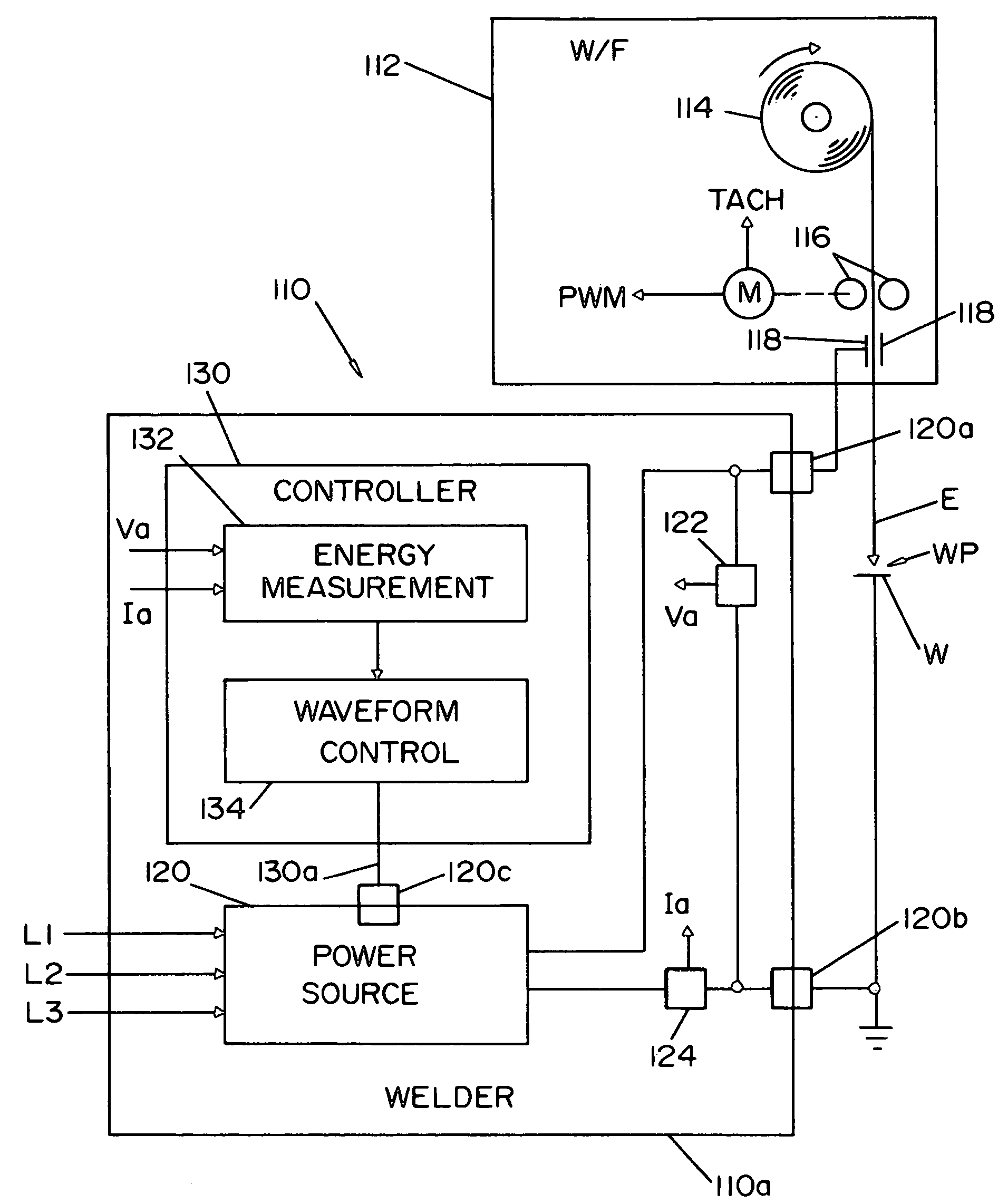
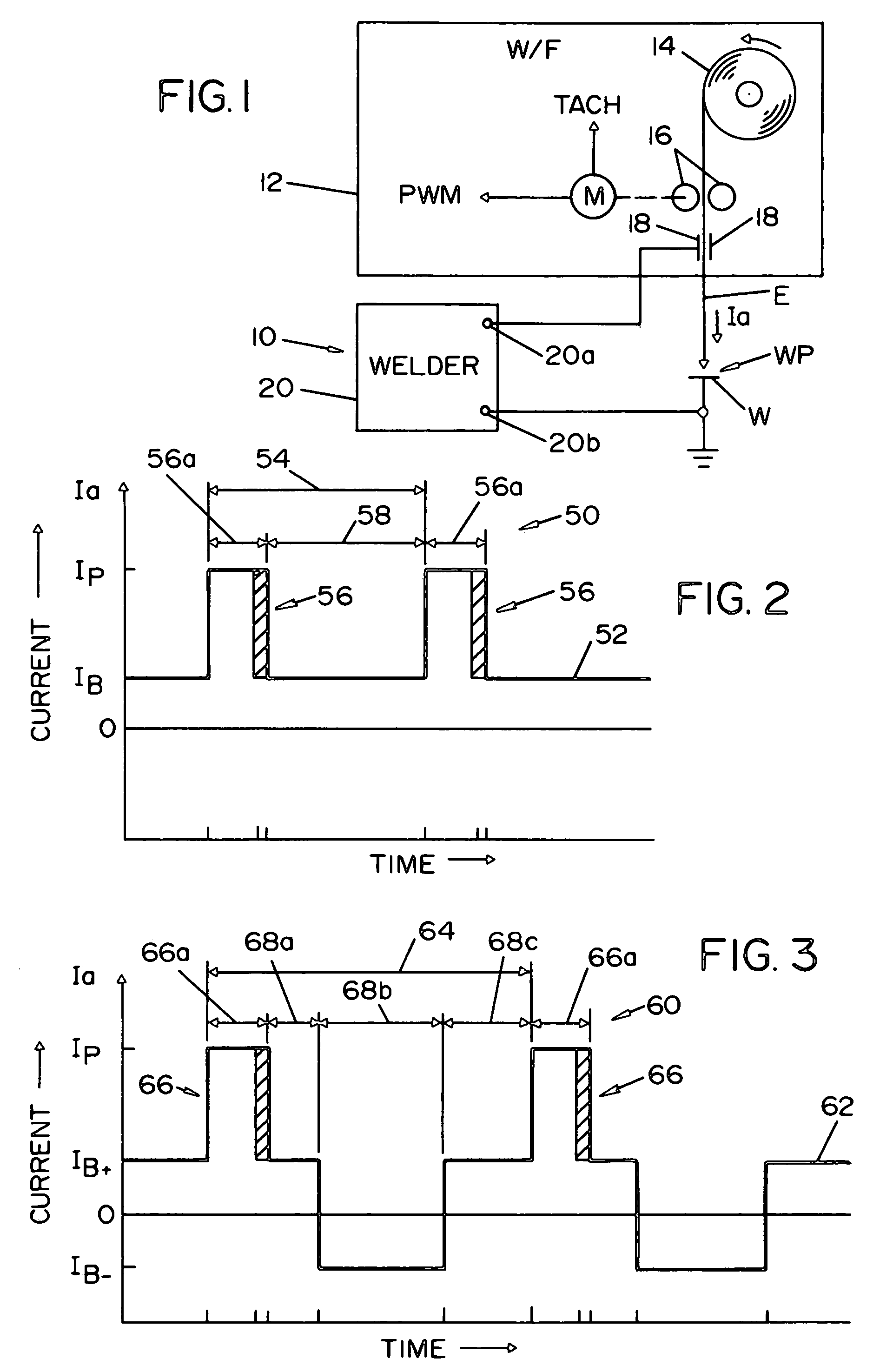
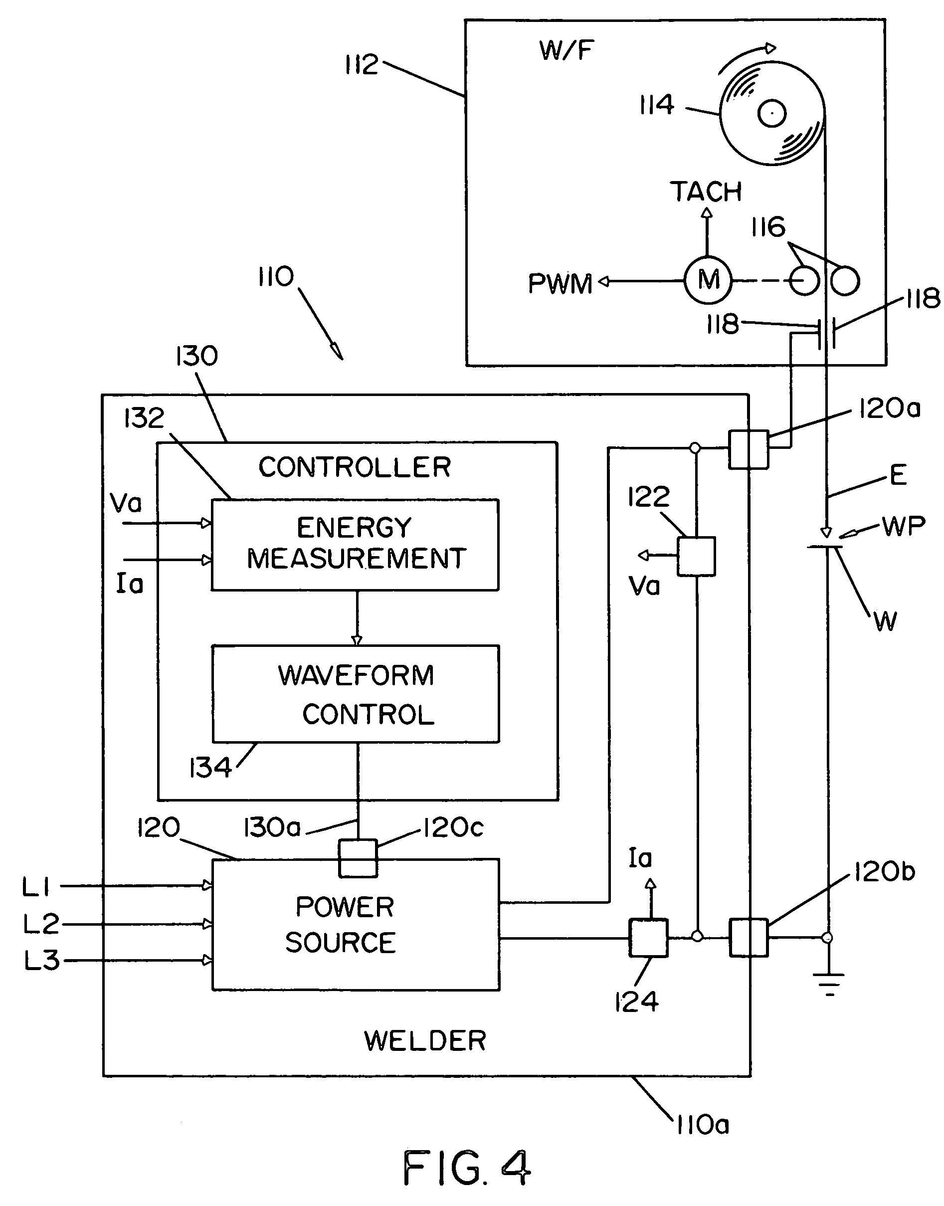
[0026]One or more embodiments or implementations of the present invention are hereinafter described in conjunction with the drawings, wherein like reference numerals are used to refer to like elements throughout and wherein the illustrated structures and waveforms are not necessarily drawn to scale. The invention relates to pulse welding methods and apparatus, and provides for controlled initiation of a transfer or release pulse based on the energy applied to a welding electrode in each pulse welding cycle. In this regard, the invention is directed to pulse welding processes and equipment in which a welder power source applies a welding signal to a consumable welding electrode in a succession of welding cycles, each cycle having a melting condition during which molten metal forms at the end of the electrode as a result of welding current from the power source, and a transfer condition in which a high current pulse in the welding signal causes the molten metal to separate from the el...


PUM

PropertyMeasurementUnit
energy measurementaaaaaaaaaa
energyaaaaaaaaaa
voltageaaaaaaaaaa

Abstract

Systems and methods are provided for pulse welding, in which a welding signal is provided to an electrode in series of pulse welding cycles, where the amount of energy applied to the electrode in each cycle is determined and a pulse is provided to initiate a transfer condition of each cycle based at least partially on the energy applied in the cycle.

Description

FIELD OF THE INVENTION[0001]The present invention relates generally to the field of welding, and more particularly to methods and systems for pulse welding.BACKGROUND OF THE INVENTION[0002]Arc welding is a process of joining metals by applying an arc to provide filler material in a molten metal pool or puddle on a workpiece. Various arc welding methodologies have been developed in which material from a consumable welding wire or electrode is melted and transferred to the workpiece. Many arc welding processes, such as metal inert gas (MIG) techniques employ a shielding gas around the welding arc to inhibit oxidation or nitridation of the molten metal. Non-inert shielding gases such as CO2 may also be used, whereby such processes are sometimes generally referred to as gas metal arc welding (GMAW). Other arc shielding processes similarly provide a protective shield of vapor or slag to cover the arc and molten weld pool. In the case of MIG welding, the molten material may be transferred...

Claims


Application Information

Patent Timeline
Patent Type & Authority Patents(United States)
IPC IPC(8): B23K9/09
CPCB23K9/093B23K9/0953B23K9/173
Inventor STAVA, ELLIOTT K.MYERS, RUSSELL K.
Owner LINCOLN GLOBAL INC
Why Eureka
Try Eureka