Electrical rotating machine control unit and power generation system

a control unit and rotating machine technology, applied in the control of electric generators, machines/engines, mechanical equipment, etc., can solve the problems of inevitability of cost increase of generators and low reliability, and achieve the effect of cost increas

Inactive Publication Date: 2007-09-18
HITACHI LTD
View PDF15 Cites 26 Cited by
  • Summary
  • Abstract
  • Description
  • Claims
  • Application Information

AI Technical Summary

Benefits of technology

[0005]According to the prior art, cost increase of the generator has been inevitable because of the necessity of resolver for detecting a rotating position, which is very expensive, and noise suppression of the rotating position signal line. In addition, the reliability is lower because of increased chances of failure. The present invention is capable of controlling a doubly-fed machine without using a rotor position sensor such as resolver, and accordingly cost increase due to the use of a rotor position sensor such as resolver in a doubly-fed machine can be prevented.
[0009]According to the present invention, cost increase due to the use of a rotor position sensor such as resolver in a doubly-fed machine can be prevented.

Problems solved by technology

According to the prior art, cost increase of the generator has been inevitable because of the necessity of resolver for detecting a rotating position, which is very expensive, and noise suppression of the rotating position signal line.
In addition, the reliability is lower because of increased chances of failure.

Method used


Image

  • Electrical rotating machine control unit and power generation system
  • Electrical rotating machine control unit and power generation system
  • Electrical rotating machine control unit and power generation system

Examples


Embodiment Construction

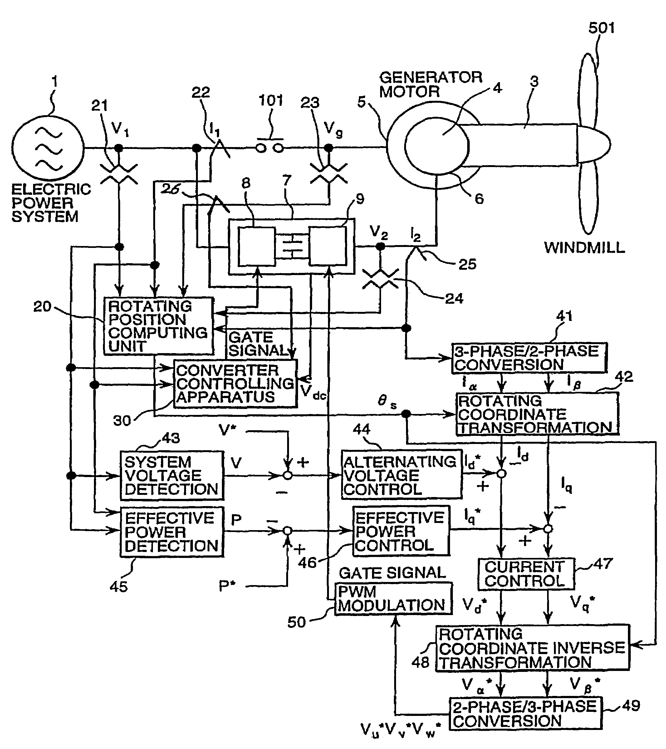
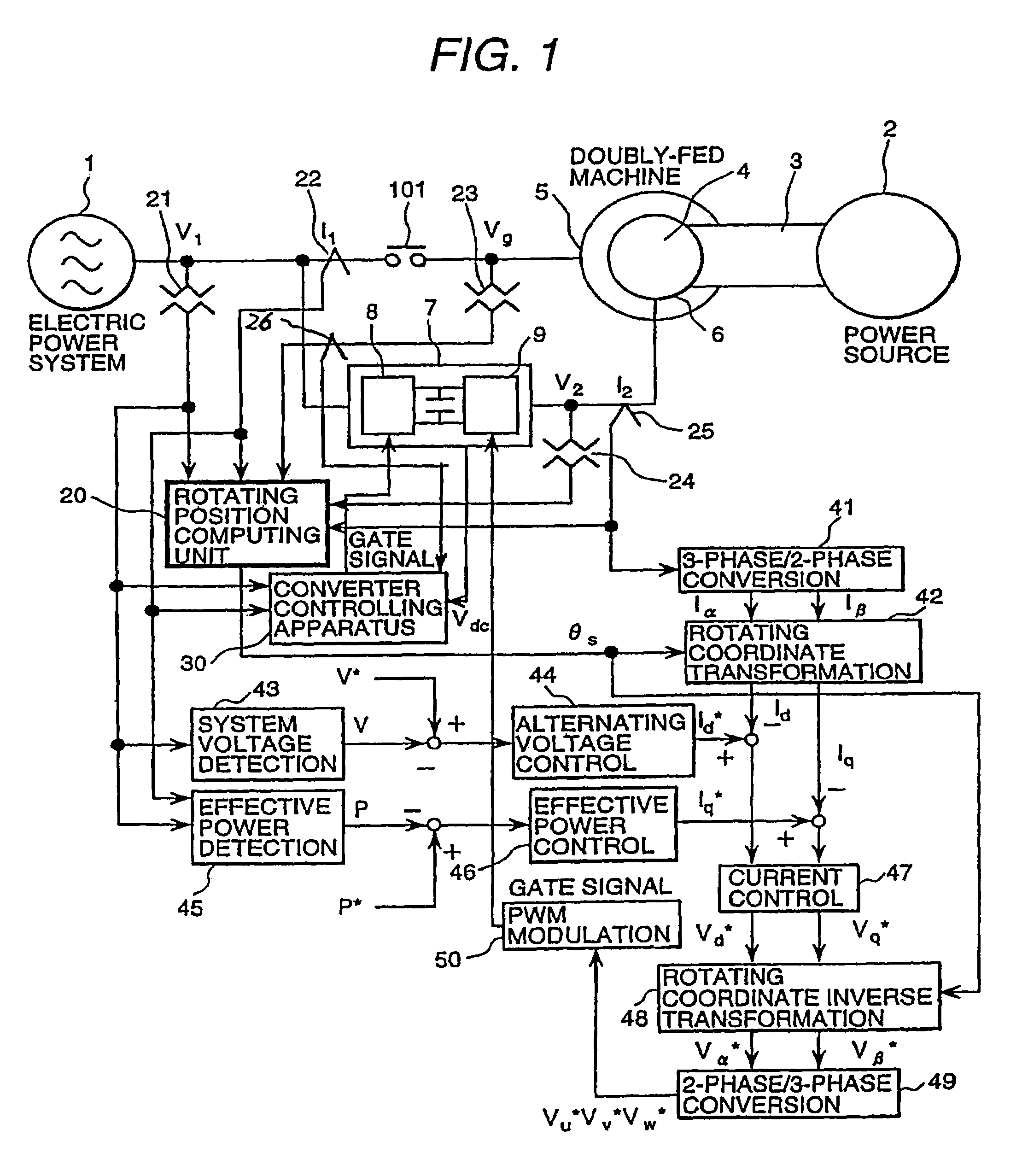
[0015]An embodiment of the present invention is described hereunder, using figures. FIG. 1 is a diagram showing the overall construction of a doubly-fed machine drive system to which the present invention applies.

[0016]As shown in FIG. 1, a doubly-fed machine 4, mechanically connected with a power source 2, is a generator-motor, equipped with 3-phase winding laid in slots provided at equal distance on the stator and rotor, that is operated at variable speed by applying variable-frequency alternating current power particularly to the secondary of the generator-motor, that is, a generator-motor which is controlled by comparing the primary voltage with a control variable in the alternating voltage control 44 so as to adjust the secondary voltage. The stator winding 5 of the doubly-fed machine 4 is connected to the electrical power system 1 via a switch 101.

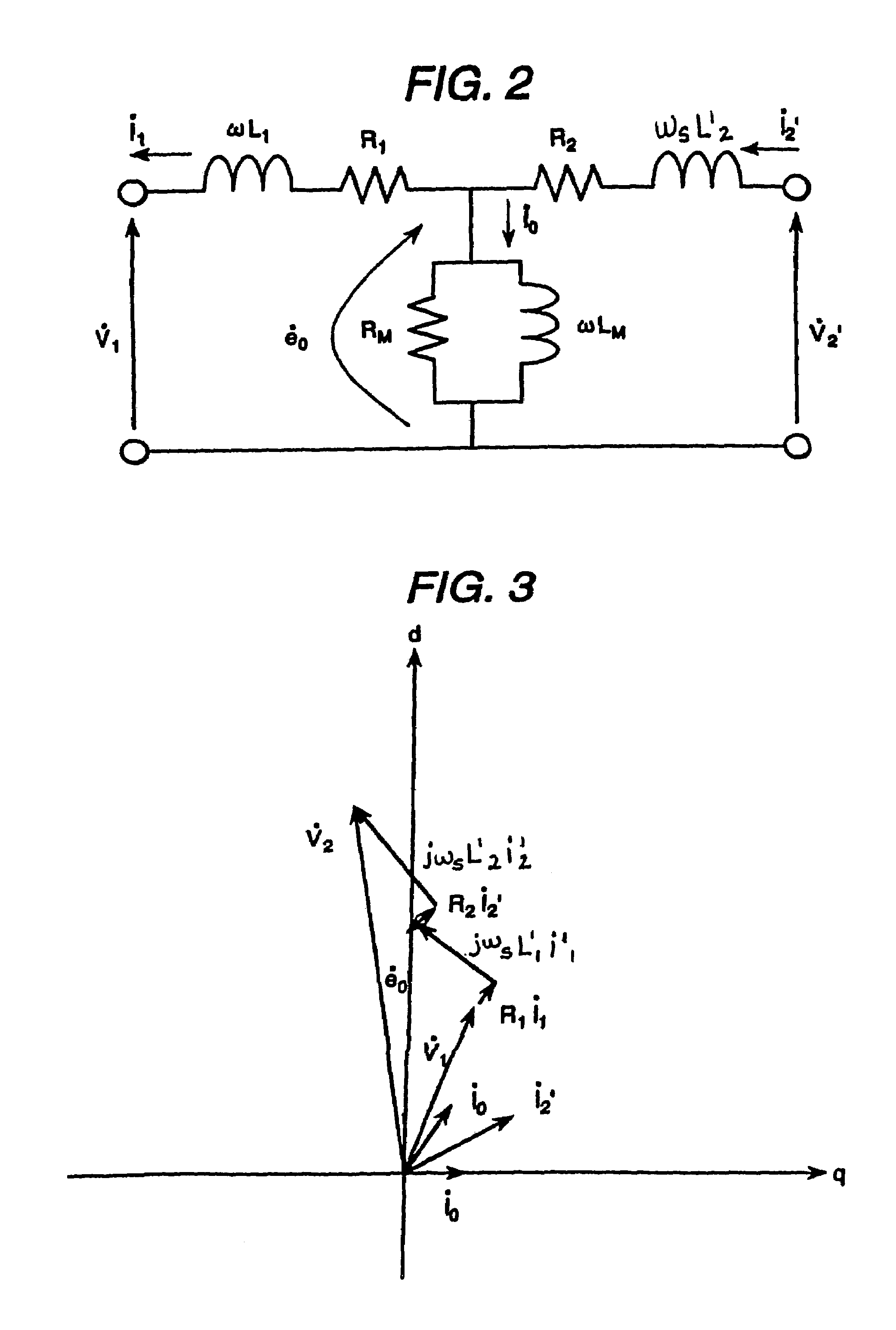
[0017]The rotor winding 6 of the doubly-fed machine 4 is electrically connected with an exciter 7 and the rotor winding 6 is altern...


PUM


Abstract

Because of the necessity of resolver for detecting a rotating position, which is very expensive, and noise suppression of the rotating position signal line on a doubly-fed machine, cost increase of the generator and reduced reliability due to possible failures are inevitable. In order to solve such problem, a generation system in the present invention is equipped with an exciter that estimates the slip frequency of the doubly-fed machine from each primary current I1 and voltage V1 and secondary current I2 and voltage V2 of the doubly-fed machine and excites the secondary of the doubly-fed machine at the estimated slip frequency.

Description

CROSS-REFERENCE TO A RELATED APPLICATION[0001]This application is a Continuation and claims priority of U.S. patent application Ser. No. 11 / 360,874, filed Feb. 23, 2006, now U.S. Pat. No. 7,157,804 B2, which is a Continuation of U.S. patent application Ser. No. 10 / 923,195, filed Aug. 20, 2004, now U.S. Pat. No. 7,095,133 B2, which claims priority of Japanese Patent Application Serial No. 2004-004900, filed on Jan. 13, 2004.BACKGROUND OF THE INVENTION[0002]The present invention relates to a rotating electrical machine control unit and power generation system, particular to a control unit and power generation system of a doubly-fed machine.[0003]Doubly-fed machine has conventionally been used as the generator for an aerogeneration system. It is a generator-motor, equipped with 3-phase winding laid in slots provided at equal distance on the stator and rotor, that is operated at variable speed by applying variable-frequency alternating current power particularly to the secondary of the ...

Claims


Application Information

Patent Timeline
Patent Type & Authority Patents(United States)
IPC IPC(8): H02P9/10
CPCH02P9/007H02P21/06H02P21/14H02P2207/076
Inventor KIMURA, MAMORUFUTAMI, MOTOOICHINOSE, MASAYAIDE, KAZUMASAIMAIE, KAZUHIRO
Owner HITACHI LTD
Why Eureka
Try Eureka