
Method and device for controlling startup of motor

a technology of synchronous resistance and motor, which is applied in the direction of electric controllers, dynamo-electric converter control, instruments, etc., can solve the problem that the rotor position detector cannot be used in the compressor of a refrigerator or air-conditioner

Active Publication Date: 2007-09-18
LG ELECTRONICS INC
View PDF2 Cites 20 Cited by
  • Summary
  • Abstract
  • Description
  • Claims
  • Application Information

AI Technical Summary

Benefits of technology

Enables the control of synchronous reluctance motor startup without motor constants, allowing for consistent operation even with changes in motor specifications without the need for extra experiments or simulations, thus improving adaptability and efficiency.

Problems solved by technology

However, the rotor position detector can not be used in a compressor for a refrigerator or air-conditioner since the internal temperature of the compressor is extremely high.
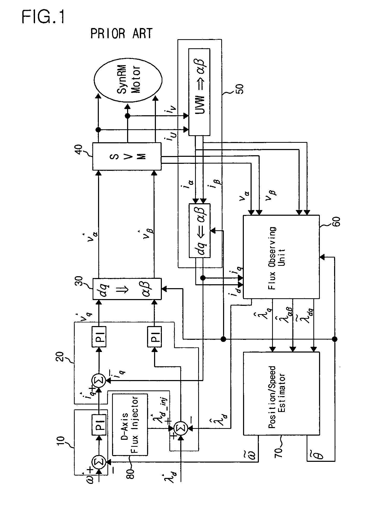
Further, there is a problem in that the obtained values are applied to a startup algorithm so that the motor should be controlled through a new startup algorithm.

Method used


Image

  • Method and device for controlling startup of motor
  • Method and device for controlling startup of motor
  • Method and device for controlling startup of motor

Examples


Embodiment Construction

[0027]Exemplary embodiments in accordance with the present invention will now be described in detail with reference to the accompanying drawings. In the following description, a detailed description of well-known functions and configurations incorporated herein will be omitted when it may make the subject matter of the present invention rather unclear.

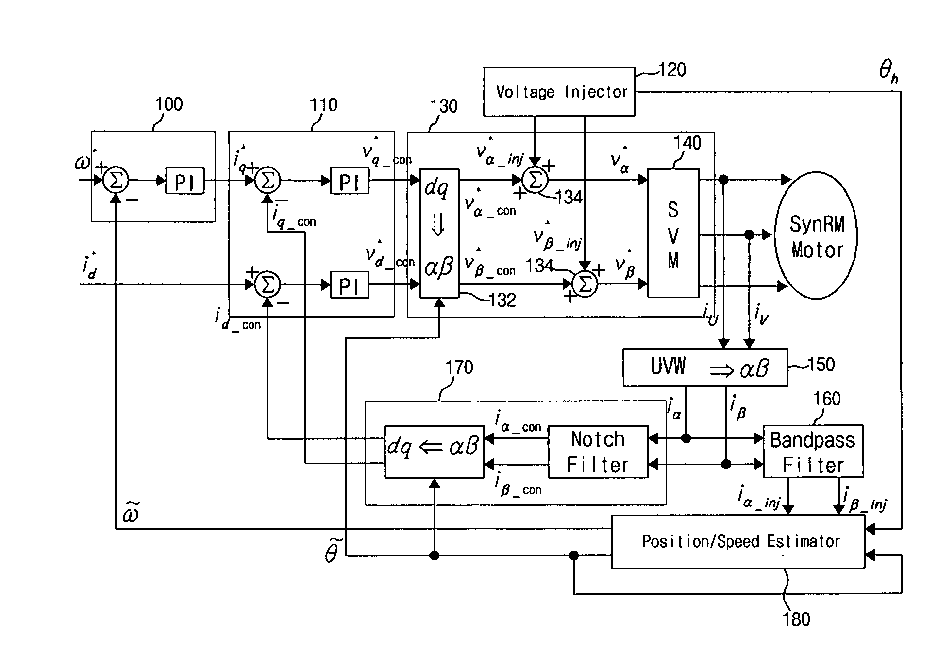
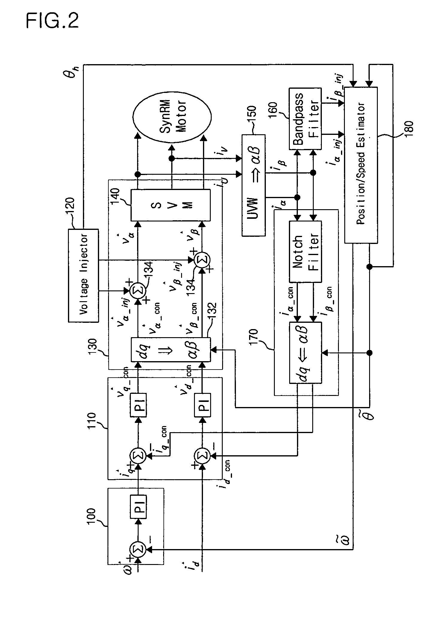
[0028]FIG. 2 is a block diagram showing a construction of a sensorless control system equipped with a device for controlling the startup of a motor in accordance with an embodiment of the present invention. FIG. 3 is a view showing an output characteristic of a voltage injector shown in FIG. 2. FIG. 4 is a view showing a detailed construction of a position / speed estimator shown in FIG. 2.

[0029]Referring to FIG. 2, the sensorless control system equipped with a device for controlling the startup of a motor in accordance with an embodiment of the present invention basically includes a reference torque current generator 100 which generates...


PUM


Abstract

Disclosed is a method and device for controlling the startup of a synchronous reluctance motor. The device includes: a voltage injector which generates injection voltages to estimate an initial position of the rotor; a motor drive voltage generator which converts stationary-coordinate-system voltages including the injection voltages to three-phase motor drive voltages and applies the three-phase motor drive voltages to the motor; a current extractor which extracts response current components iα-inj, iβ-inj in respect to the injection voltages from two-phase stationary-coordinate-system currents converted from three-phase currents detected upon rotation of the motor; and a position / speed estimator which extracts response current components related to a rotor position from the response current components iα-inj, iβ-inj in respect to the injection voltages to calculate a rotor position error (e), and estimates the speed and position {tilde over (ω)},{tilde over (θ)} of the rotor from the calculated rotor position error (e).

Description

BACKGROUND OF THE INVENTION[0001]This application claims the priority of Korean Patent Application No. 2004-101840, filed on Dec. 6, 2004, in the Korean Intellectual Property Office, the disclosure of which is incorporated herein in its entirety by reference.[0002]1. Field of the Invention[0003]The present invention relates to a method and device for controlling a motor and, more particularly, to a method and device for controlling the startup of a synchronous reluctance motor.[0004]2. Description of Related Art[0005]A synchronous reluctance motor implies one configured such that a driving source of a rotor is synchronous with that of a stator and the rotor rotates so that a resistance created in the rotor can be minimized when a current flows into the stator. To drive such a synchronous reluctance motor, the position of the rotor should be known. The position of the rotor can be directly detected by use of a rotor-position detector, such as an encoder. However, the rotor position d...

Claims


Application Information

Patent Timeline
Patent Type & Authority Patents(United States)
IPC IPC(8): G05B11/36
CPCH02P1/163H02P25/08H02P6/183
Inventor LEE, GIL-SUCHEONG, DAL-HOLEE, KYUNG-HOON
Owner LG ELECTRONICS INC
Learn More