
Method and apparatus for reducing crosstalk and nonlinear distortions induced by raman interactions in a wavelength division mulitplexed (WDM) optical communication system

a wavelength division mulitplex and optical communication technology, applied in the field of wavelength division multiplexed optical signals, can solve the problems of raman crosstalk, degrade the quality of optically transmitted information, corrupt the information being transmitted by optical signals, etc., and achieve the effect of reducing raman crosstalk and raman crosstalk

Active Publication Date: 2007-09-18
GOOGLE TECH HLDG LLC
View PDF5 Cites 21 Cited by
  • Summary
  • Abstract
  • Description
  • Claims
  • Application Information

AI Technical Summary

Benefits of technology

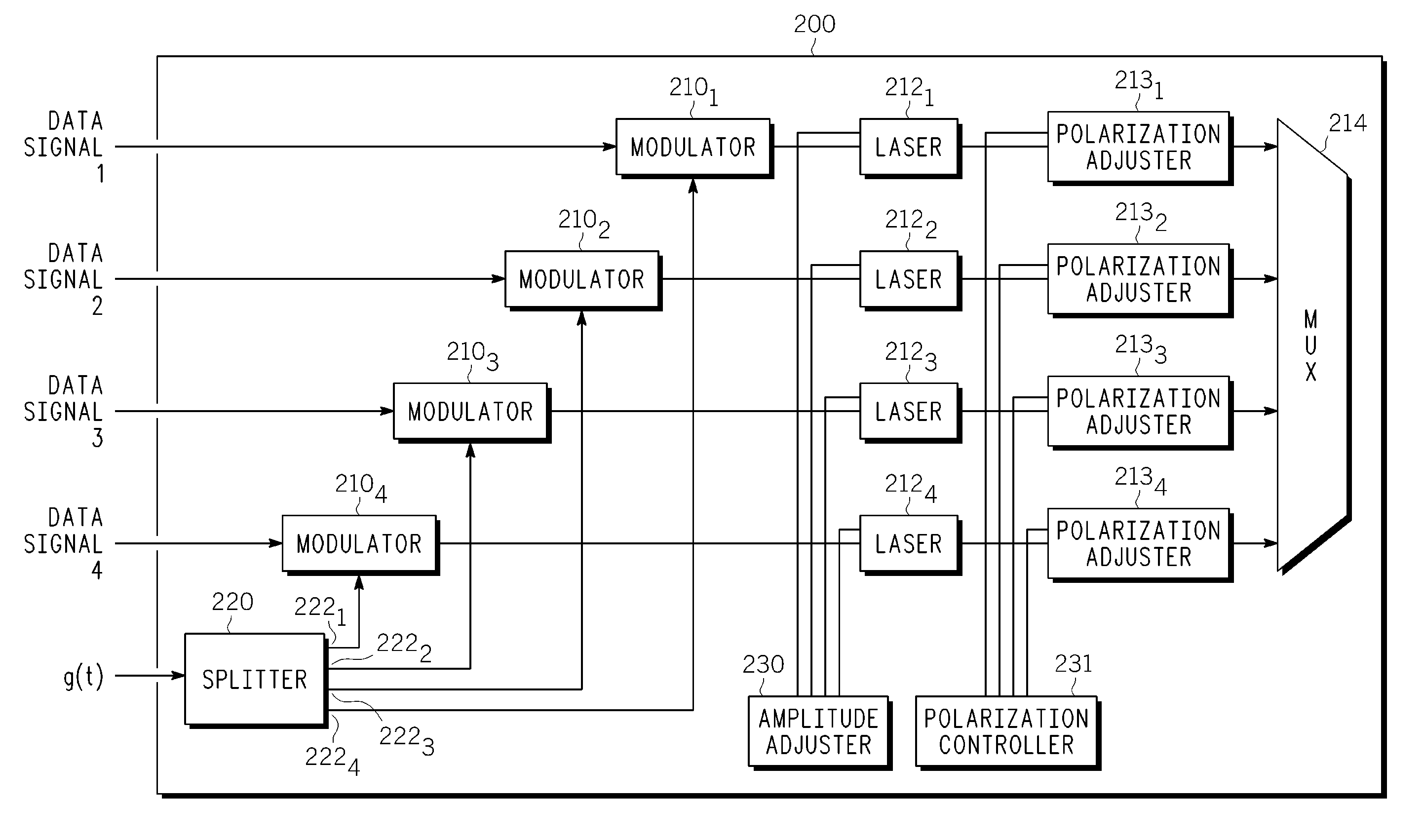
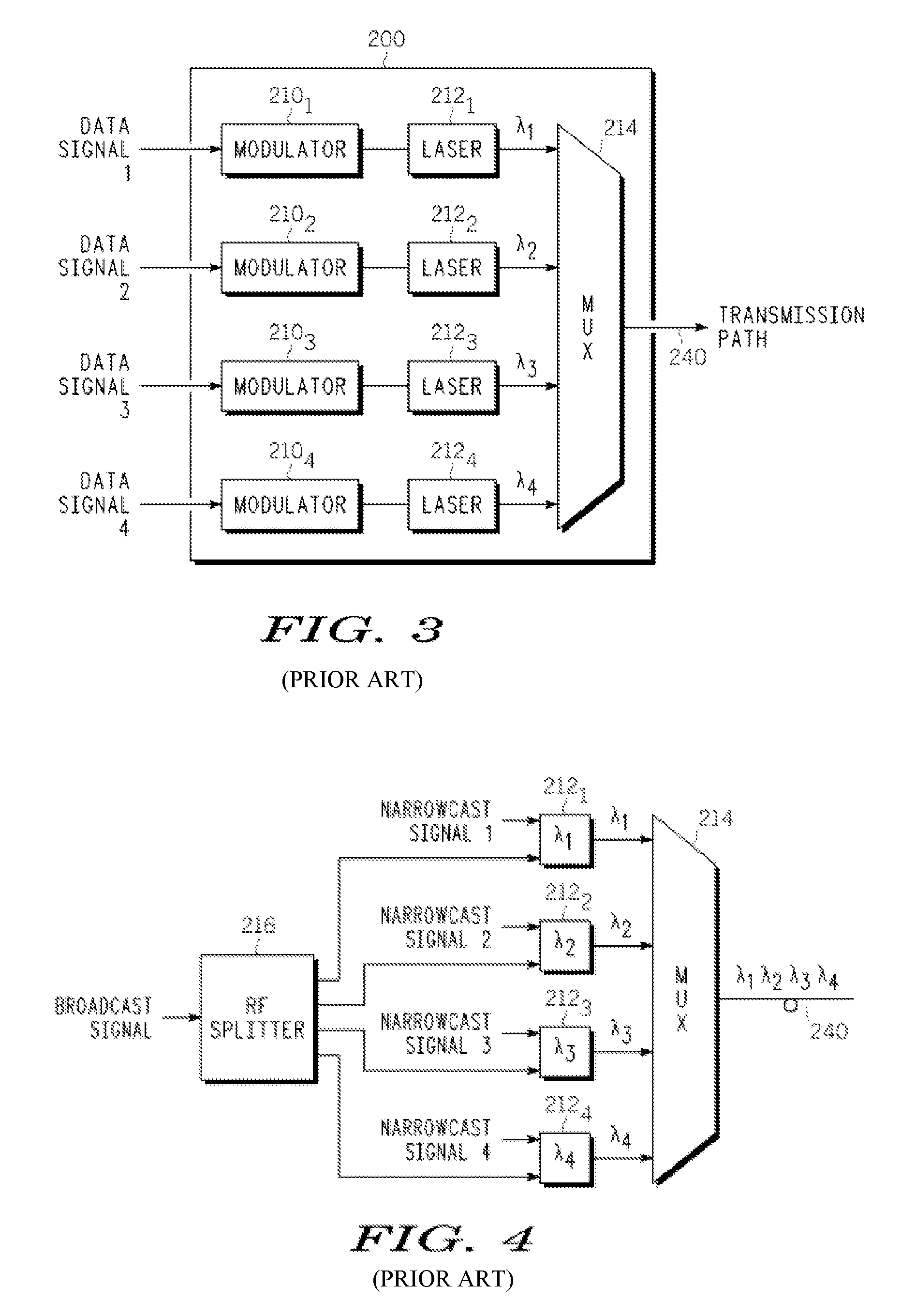
This patent describes a method and apparatus for transmitting a wavelength division multiplexing (WDM) optical signal. The method involves modulating multiple optical channels with different information-bearing broadcast signals that all have the same broadcast information. The broadcast signals are combined to form a WDM optical signal, which is then transmitted onto an optical transmission path. The patent also describes various aspects that can be used to reduce interference and distortion in the optical signal, such as applying a phase shift to one of the broadcast signals, combining narrowcast signals with the broadcast signals, adjusting the relative amplitudes and polarization of the optical channels, and using a dispersion-compensated optical transmission path. The patent also describes the components of a WDM optical transmitter that can be used to implement the method. Overall, the patent provides technical means to improve the quality and stability of WDM optical signals in optical transmission systems.

Problems solved by technology

Although WDM optical transmission systems have increased the speed and capacity of optical networks, the performance of such systems is limited by various factors such as chromatic dispersion and the fiber nonlinearity, which can cause pulse shape change in the case of baseband digital signals and distortions in case of analog signals.
These impairments degrade the quality of the optically transmitted information.
If the level of crosstalk is sufficiently large it will corrupt the information being transmitted by the optical signals impacted by this impairment.
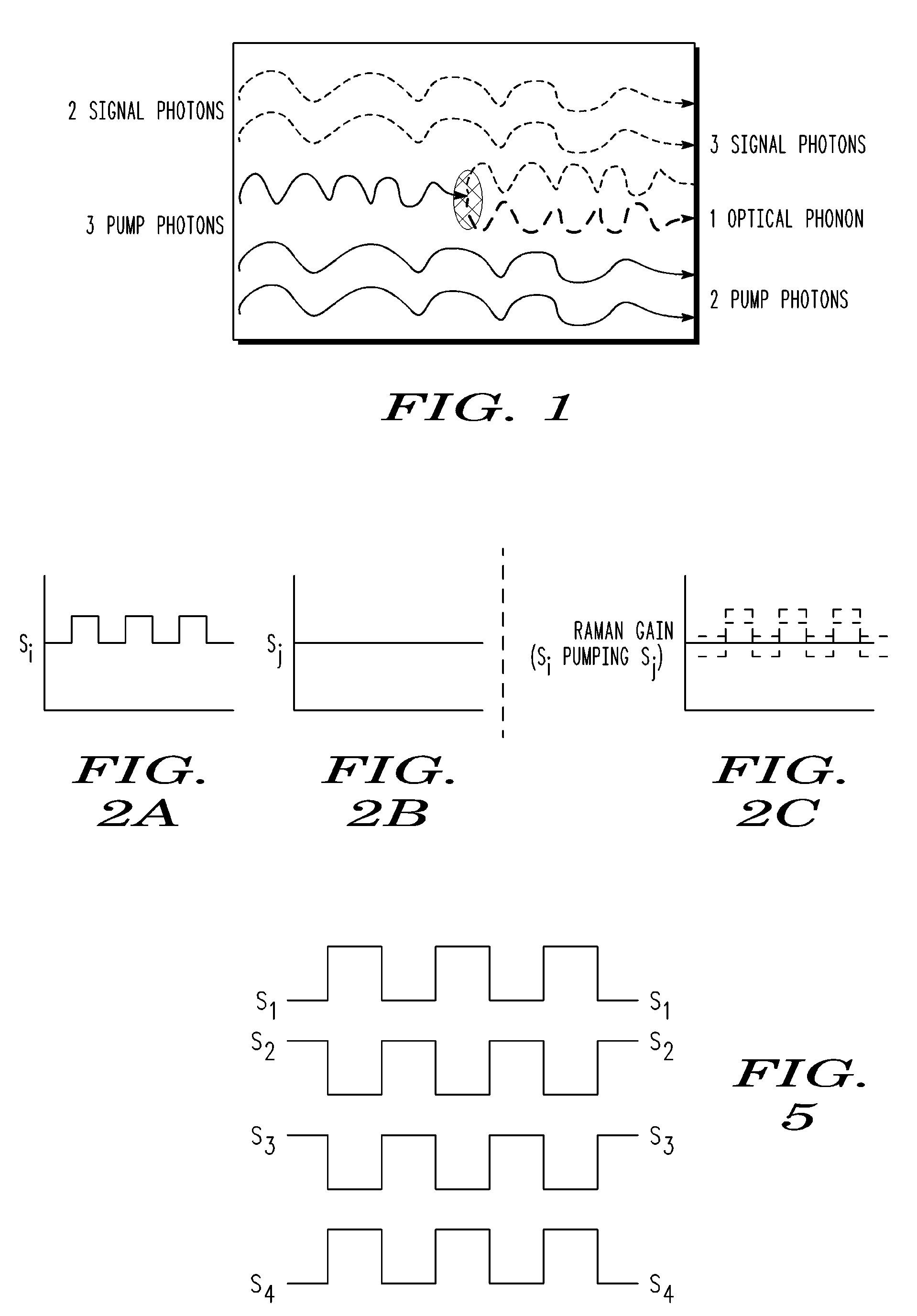
Problems arise, however, when both the pump and signal wavelengths are modulated.
The crosstalk can interfere with and degrade the quality of the original information being transmitted by the signal wavelength.
Therefore, at points in time-space where the signal wavelength is peaked, due to the modulation it carries, the pump will more easily lose photons during SRS.
This crosstalk can interfere with and degrade the quality of the original information being transmitted by the pump wavelength.
In a multiple wavelength system (three or more wavelengths) the crosstalk process is similar to what has already been described but the complexity grows since now there are multiple pumping sources and multiple signals generating crosstalk on each of the optical waves.
The Raman crosstalk is a problem for both analog and digital modulation schemes.
In addition to the generation of unwanted crosstalk the SRS process can also lead to the generation of Raman induced second order (CSO: composite second order) and third order (CTB: composite triple beat) distortions.
If the pump and signal lasers' modulations are not in phase with one another interference can also result between the various terms within each line of (4).
The levels of Raman induced crosstalk and distortions are much lower in the nonzero dispersion scenario because, as the signals walk away from one another, it becomes more difficult for the crosstalk and distortions to build up constructively along the fiber length.

Method used


Image

  • Method and apparatus for reducing crosstalk and nonlinear distortions induced by raman interactions in a wavelength division mulitplexed (WDM) optical communication system
  • Method and apparatus for reducing crosstalk and nonlinear distortions induced by raman interactions in a wavelength division mulitplexed (WDM) optical communication system
  • Method and apparatus for reducing crosstalk and nonlinear distortions induced by raman interactions in a wavelength division mulitplexed (WDM) optical communication system

Examples


Embodiment Construction

[0045]Equations (4) and (5) presented above are the starting points in the discussion on eliminating the undesired Raman induced crosstalk and distortions that occur in a near zero dispersion optical communication system. Suppose that a constant phase shift can be applied to the composite RF subcarrier modulation applied to each transmitter. This can be accomplished by means of a broadband phase shifter such as a transformer based all pass filter that has a constant phase shift across the RF band of the subcarriers. The composite modulation signal feeding each transmitter is run though such a phase shifter specifically tailored for each laser with a specified phase. For the two wavelength system if a phase shift of φs is applied to the signal laser and phase shift of φp is applied to the pump laser equation (4) is then modified to the following in the frequency domain:

[0046] Ps⁡(f,L)=⁢P0⁢s⁡[1+Gsp⁢ρ_L⁢Leff⁢P0⁢p]⁢ⅇ-α⁢⁢L+⁢P0⁢s⁢ms⁢ⅇⅈ⁢⁢φs⁢⁡[fs⁡(t)]+⁡[1+Gsp⁢ρ_L⁢Leff⁢P0⁢p]⁢ⅇ-α⁢⁢L+⁢Gsp⁢ρ_L⁢...


PUM


Abstract

A method and apparatus is provided for transmitting a WDM optical signal. The method begins by modulating a plurality of optical channels that are each located at a different wavelength from one another with (1) a respective one of a plurality of information-bearing electrical signals that all embody the same broadcast information and (2) a respective one of a plurality of RF signals having a common functional broadcast waveform, at least one of the RF signals being out of phase with respect to remaining ones of the plurality of RF signals. Each of the modulated optical channels are multiplexed to form a WDM optical signal. The WDM optical signal is forwarded onto an optical transmission path.

Description

FIELD OF THE INVENTION[0001]The invention relates generally to the transmission of wavelength division multiplexed (WDM) optical signals, and more particularly to a method and apparatus for reducing crosstalk and nonlinear signal distortions induced by Raman interactions between the optical channels.BACKGROUND OF THE INVENTION[0002]In recent years wavelength division multiplexed (WDM) optical transmission systems have been increasingly deployed in optical networks. These include coarse wavelength division multiplexed (CWDM) and dense wavelength division multiplexed (DWDM) systems. Whether a system is considered to be CWDM or DWDM simply depends upon the optical frequency spacing of the channels utilized in the system. Although WDM optical transmission systems have increased the speed and capacity of optical networks, the performance of such systems is limited by various factors such as chromatic dispersion and the fiber nonlinearity, which can cause pulse shape change in the case of...

Claims


Application Information

Patent Timeline
Patent Type & Authority Patents(United States)
IPC IPC(8): H01S3/00
CPCH04B10/2537H04J14/0226H04J14/0282H04J14/0298H04J14/0247H04J14/0252H04J14/0232H04J14/0246H04J14/0227
Inventor WANG, JUN JLITVIN, KERRY
Owner GOOGLE TECH HLDG LLC
Learn More