Muffler with internal heat shield

a technology of internal heat shield and muffler, which is applied in the direction of mechanical equipment, machines/engines, transportation and packaging, etc., can solve the problems of packaging not performing a significant heat insulation function, and achieve the effect of less cos

Inactive Publication Date: 2007-09-25
FAURECIA EXHAUST SYST
View PDF36 Cites 24 Cited by
  • Summary
  • Abstract
  • Description
  • Claims
  • Application Information

AI Technical Summary

Benefits of technology

[0018]The muffler may be manufactured at least partly from stamp formed components. In particular, the muffler may comprise first and second outer shells each of which has a peripheral flange and at least one chamber extending from the peripheral flange. The peripheral flanges of the first and second outer shells may be dimensioned and configured to register with one another. The first outer shell may be an upper outer shell disposed to nest in a selected space on the underside of the vehicle. The heat shielding high-density fiber insulation pad may be disposed to nest with the inner surface of the upper outer shell, and hence functions to shield adjacent areas of the vehicle from heat generated by the muffler.

Problems solved by technology

However, the density of the fiberglass or E-glass packing for performing the noise insulating function prevents the packing from performing a significant heat insulating function.

Method used


Image

  • Muffler with internal heat shield
  • Muffler with internal heat shield
  • Muffler with internal heat shield

Examples


Embodiment Construction

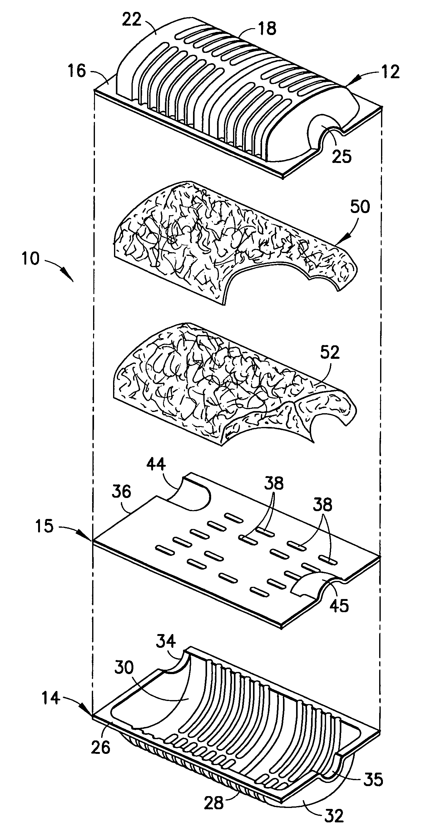
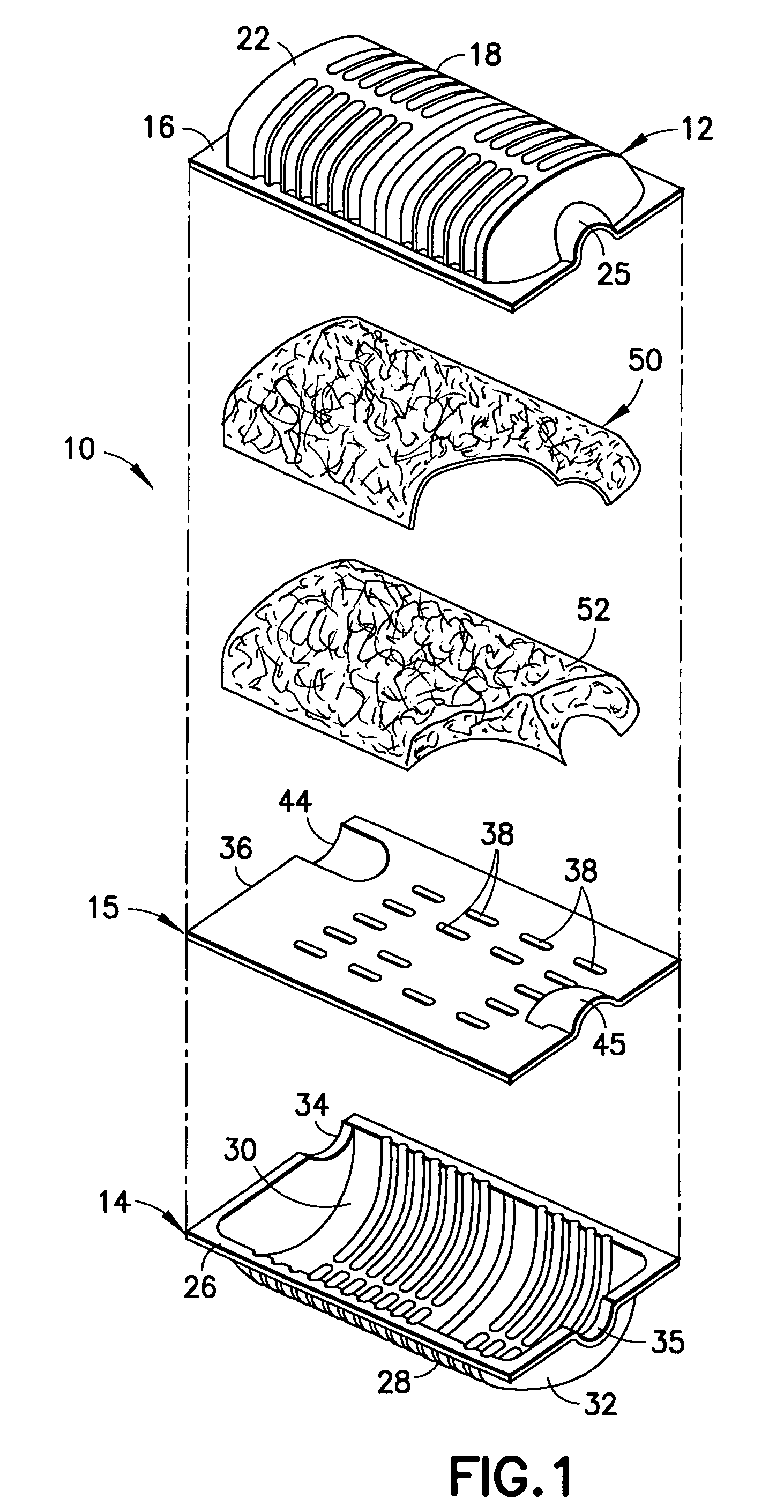
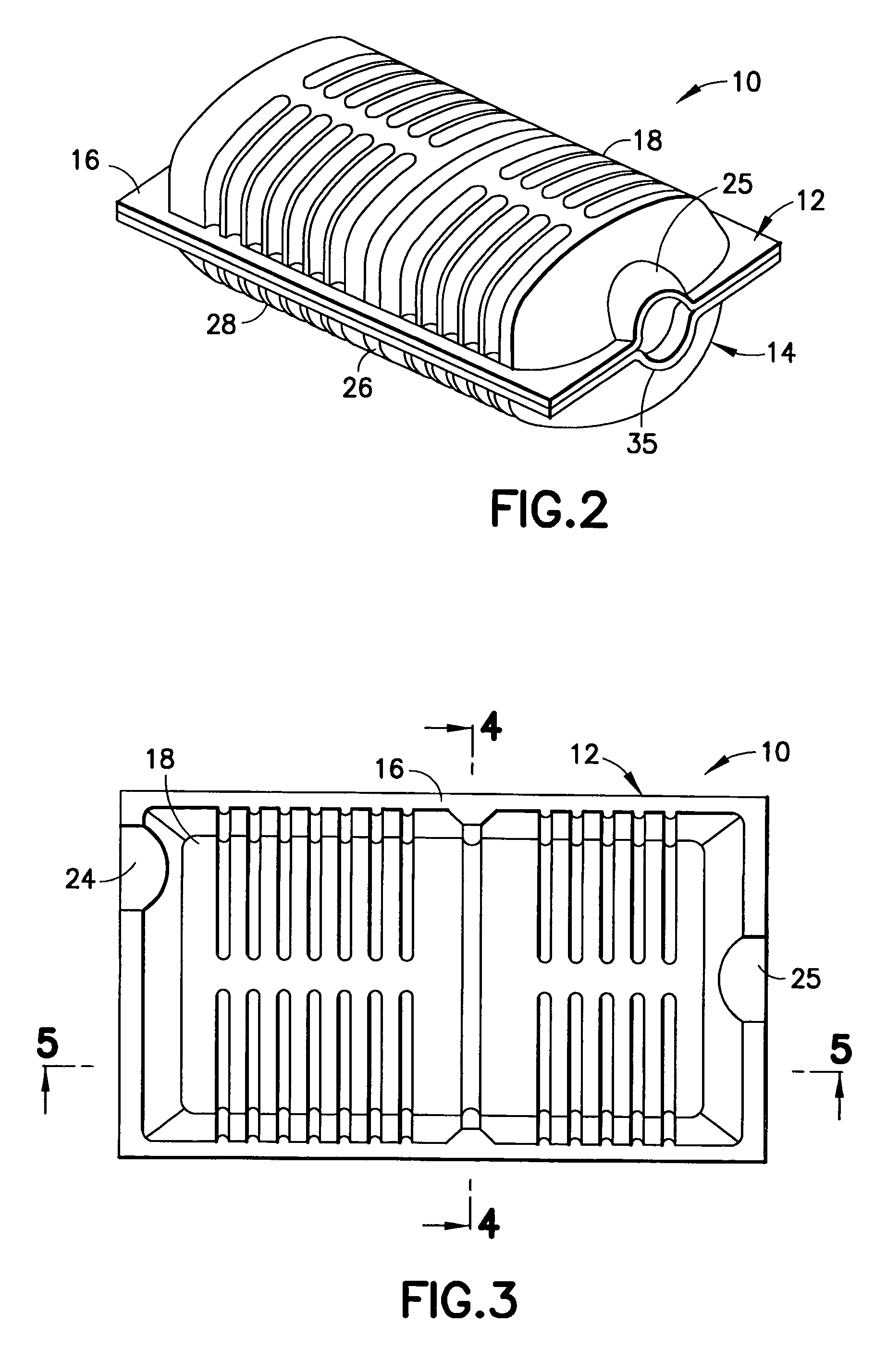
[0026]A muffler in accordance with the subject invention is identified generally by the numeral 10 in FIGS. 1 through 5. The muffler 10 includes upper and lower external shells 12 and 14 and an internal plate 15 that are stamped or otherwise formed from a metallic material. The upper external shell 12 includes a generally planar peripheral flange 16 and a chamber 18 extending upwardly and out of the plane defined by the peripheral flange. The upper external shell 12 includes a generally concave inner surface 20 and a generally convex outer surface 22. Additionally, the upper external shell 12 includes an inlet channel 24 and an outlet channel 25 each of which extends from the peripheral flange 16 into communication with the concave inner surface 20 of chamber 18.

[0027]The lower external shell 14 includes a planar peripheral flange 26 and a chamber 28 extending downwardly and out of the plane defined by the peripheral flange 26. The chamber 28 defines a concave inner surface 30 and a...


PUM


Abstract

An exhaust muffler includes upper and lower external shells that are formed from metal material. A heat shield is disposed in the muffler adjacent the upper external shell. The heat shield is formed from a high-density fiber insulation pad configured to nest with the concave inner surface of the upper external shell.

Description

[0001]This application claims priority on U.S. Provisional Patent Appl. No. 60 / 500,500, filed Sep. 5, 2003.BACKGROUND OF THE INVENTION[0002]1. Field of the Invention[0003]The invention relates to a heat-shielded vehicular exhaust muffler.[0004]2. Description of the Related Art[0005]The combustion that takes place in the engine of an automotive vehicle produces substantial amounts of heated noxious gas and significant amounts of noise. As a result, all automotive vehicles include an exhaust system that transports the exhaust gas from the engine to a location on the vehicle where the heat exhaust gas can be emitted safely. Additionally, the exhaust system includes components to convert certain of the noxious compounds in the exhaust gas into less noxious gases. Components of the exhaust system also function to attenuate the noise associated with the flowing and rapidly expanding gases produced by the combustion processes in the engine.[0006]The typical exhaust system extends from the ...

Claims


Application Information

Patent Timeline
Patent Type & Authority Patents(United States)
IPC IPC(8): F01N1/24F01N1/10F01N1/00F01N7/18B60K13/04F01N1/04F01N13/14F01N13/18
CPCF01N1/04F01N1/24F01N13/14F01N13/1872F01N1/10F01N2310/02F01N2470/08F01N2490/04
Inventor HARWOOD, JON W.
Owner FAURECIA EXHAUST SYST
Why Eureka
Try Eureka