Union coupler assembly for coolant lines

Inactive Publication Date: 2007-09-25
PLATTNER WESLEY M
View PDF15 Cites 19 Cited by
  • Summary
  • Abstract
  • Description
  • Claims
  • Application Information

AI Technical Summary

Benefits of technology

[0006]The first and second coolant line end portions are formed of metal, and each coolant line end portion has a tapered end and a groove formed in its outer surface for receiving a snap ring. The first and second coolant line end portions are movable between an engaged position, wherein one of the first and second snap rings engages the groove in one of the first or second coolant line end portions, and the other snap ring engages the groove in the other coolant line end portion, and a disengaged position, wherein neither of the snap rings engage the groove in

Problems solved by technology

Connecting air conditioning lines on aircraft poses significant difficulty.
Due to the risk of fire or explosion, the copper or aluminum piping cannot be welded while performing maintenance on an aircraft.
Although flares or fittings are useful for similar applications, they have proven ineffective for aircraft cooling systems due to the leaking of such flares and fittings caused by the small molecules formed in the coolant.
These radial forces may cause deformation of the coupler or the pipe, thereby causing the pipe to separate from the coupler.
When compressive forces are exerted on the coupler by the fluid filled line, the contractible ring may also travel inward past the circumferentially tapered channel, causing the fluid filled line to become stuck in the coupler.

Method used


Image

  • Union coupler assembly for coolant lines
  • Union coupler assembly for coolant lines
  • Union coupler assembly for coolant lines

Examples


Embodiment Construction

[0014]Referring to the drawings, the present invention will now be described in detail with reference to the preferred embodiment.

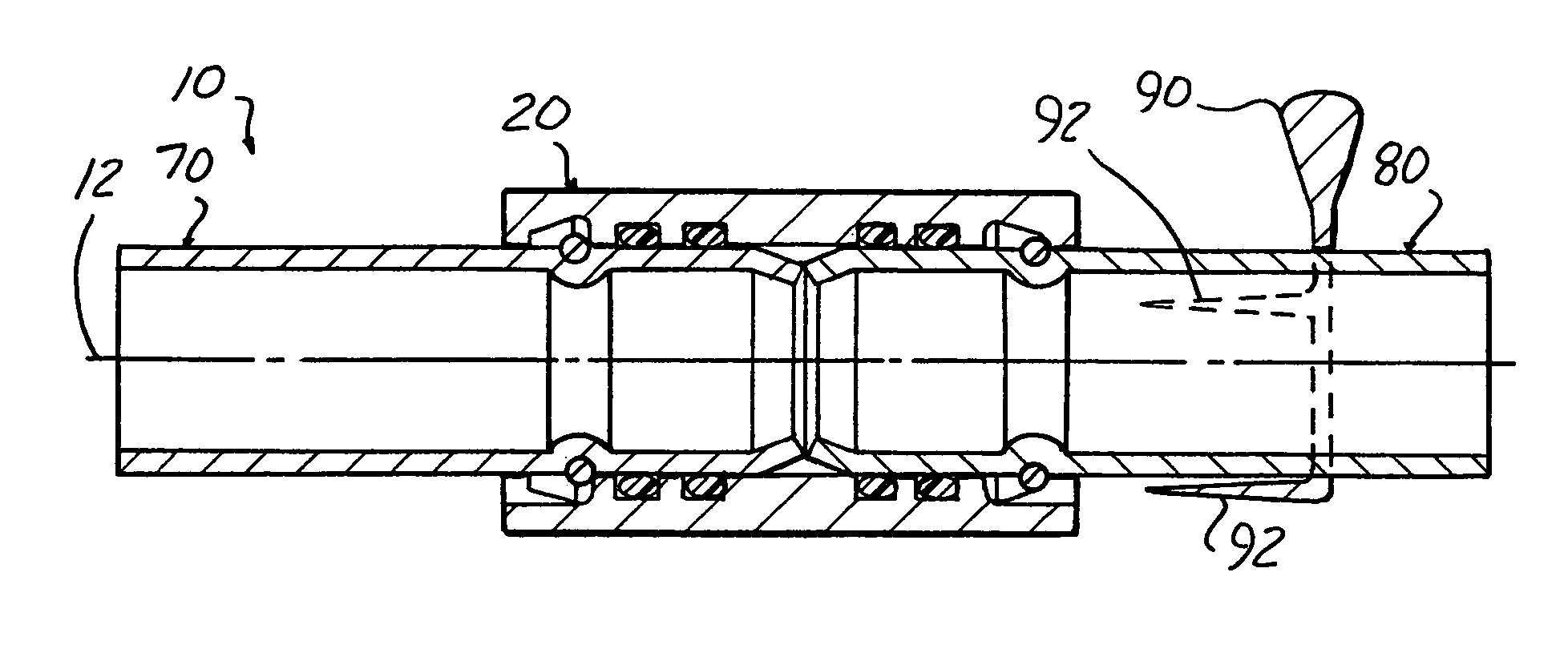
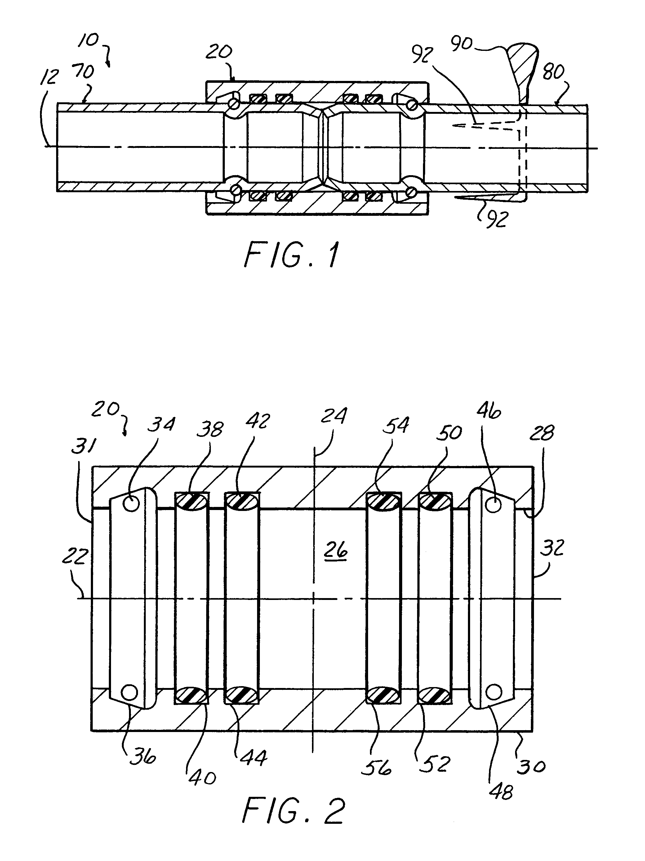
[0015]FIG. 1 shows the union coupler assembly 10 of the present invention. The union coupler assembly 10 provides a coupler body 20 that sealingly enables fluid communication between coolant lines of an air conditioning system (not shown) on an aircraft (not shown). Although the present invention is ideally suited for aircraft, the present invention is not limited to aircraft, but rather, the present invention may be utilized to couple any air conditioning lines for any system. A first coolant line end portion 70 and a second coolant line end portion 80 of the air conditioning coolant lines have an engaged position, wherein the first and second coolant line end portions 70, 80 are held in sealed engagement with the coupler body 20 so that fluid, such as air conditioning coolant, may flow between the first and second coolant line end portions 70, 80, and a...


PUM


Abstract

A union coupler assembly for coolant lines comprising a coupler body, a first coolant line end portion, and a second coolant line end portion. The coupler body has a passageway extending between first and second ends, two tapered annular grooves, a snap ring disposed within each tapered annular groove, and a plurality of o-rings seated in corresponding annular grooves. The coolant line end portions are fabricated from metal and have tapered ends and grooves formed in their outer surfaces. The coolant line end portions are movable between an engaged position, wherein the snap rings engage the grooves in the coolant line end portions, and a disengaged position, wherein the snap rings do not engage the grooves in the coolant line end portions. When the coolant line end portions are in the engaged position, the tapered end of the first coolant line end portion abuts the tapered end of the second coolant line end portion to prevent inward movement of the coolant line end portions, and at least one o-ring seals each coolant line end portion with respect to the coupler body.

Description

FIELD OF THE INVENTION[0001]The present invention relates to the field of union coupler assemblies, and more particularly, the present invention relates to a union coupler assembly for connecting a pair of air conditioning coolant lines having a coupler body that sealingly couples a first coolant line and a second coolant line.BACKGROUND OF THE INVENTION[0002]Connecting air conditioning lines on aircraft poses significant difficulty. Air conditioning coolant lines on aircraft are typically fabricated from copper or aluminum piping. Due to the risk of fire or explosion, the copper or aluminum piping cannot be welded while performing maintenance on an aircraft. Although flares or fittings are useful for similar applications, they have proven ineffective for aircraft cooling systems due to the leaking of such flares and fittings caused by the small molecules formed in the coolant.[0003]Past coupler designs have been produced to connect two fluid filled lines wherein a contractible ring...

Claims


Application Information

Patent Timeline
IPC IPC(8): F16L37/00
CPCF16L37/088F16L37/0887
Inventor PLATTNER, WESLEY M.
Owner PLATTNER WESLEY M
Why Eureka
Try Eureka