Fuel cell power generating system

a technology of fuel cell and power generation system, which is applied in the direction of fuel cells, solid electrolyte fuel cells, electrical equipment, etc., can solve the problems of only eliminating rough dust, not eliminating fine dust, salt or other impurities, and reducing gas dissipation ability or so as to improve cell output properties, reduce the effect of gas dissipation ability or the reduction of electric conductance of solid polymer films

Inactive Publication Date: 2007-09-25
SANYO ELECTRIC CO LTD
View PDF5 Cites 4 Cited by
  • Summary
  • Abstract
  • Description
  • Claims
  • Application Information

AI Technical Summary

Benefits of technology

[0019]The present invention can supply the air pole of a fuel cell with a clean air free from impurities, by providing the reaction air supply apparatus with an impurities elimination means for removing fine dust, salt or the like in the air. As a result, the cell output properties can be improved by preventing the decrease of gas dissipation ability or the decrease of electric conductance of the solid polymer film provoked by impurities.
[0020]Moreover, it becomes possible to wet approximately evenly the humidification filter with supplied water and keep its wet state, by using, for instance, a sheet shape porous material presenting a high water absorption, as humidification filter, and it can be intended to increase the ability to capture impurities in the air and improve the electric conductance by humidifying conveniently the solid polymer film with humidified air. Further, the provision of humidification filter in the oxidant gas supply passage allows to supply the fuel cell body with air in humidified state, to keep the humidified state of the solid polymer film and to maintain a good electric conductance of the solid polymer film.

Problems solved by technology

By the way, said reaction air supply apparatus D of the prior art certainly removes dust contained in the air (atmosphere) and purifies as mentioned above; however, in practice, it removes only rough dust, and can not eliminate fine dust, salt or other impurities.

Method used


Image

  • Fuel cell power generating system
  • Fuel cell power generating system
  • Fuel cell power generating system

Examples


Embodiment Construction

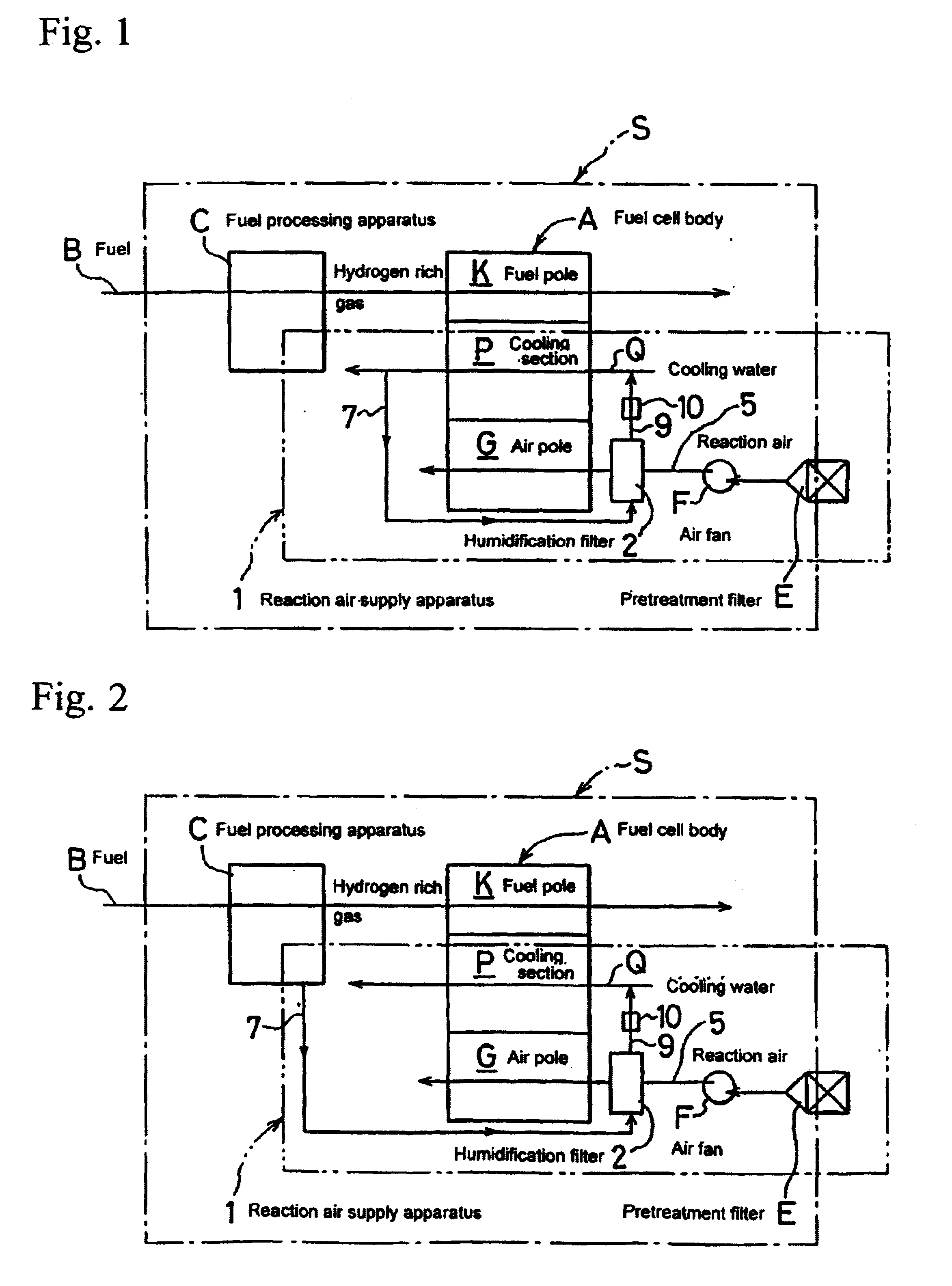
[0028]Next, the embodiment of air supply apparatus for cell according to the invention will be described based on attached drawings. Here, the same composition members as the prior art will have the same symbol to facilitate the comprehension of the invention. In FIG. 1, 1 is a reaction air supply apparatus in a fuel cell power generation system 1, comprising a pretreatment filter E, an air fan F, and a humidification filter 2 humidified with water.

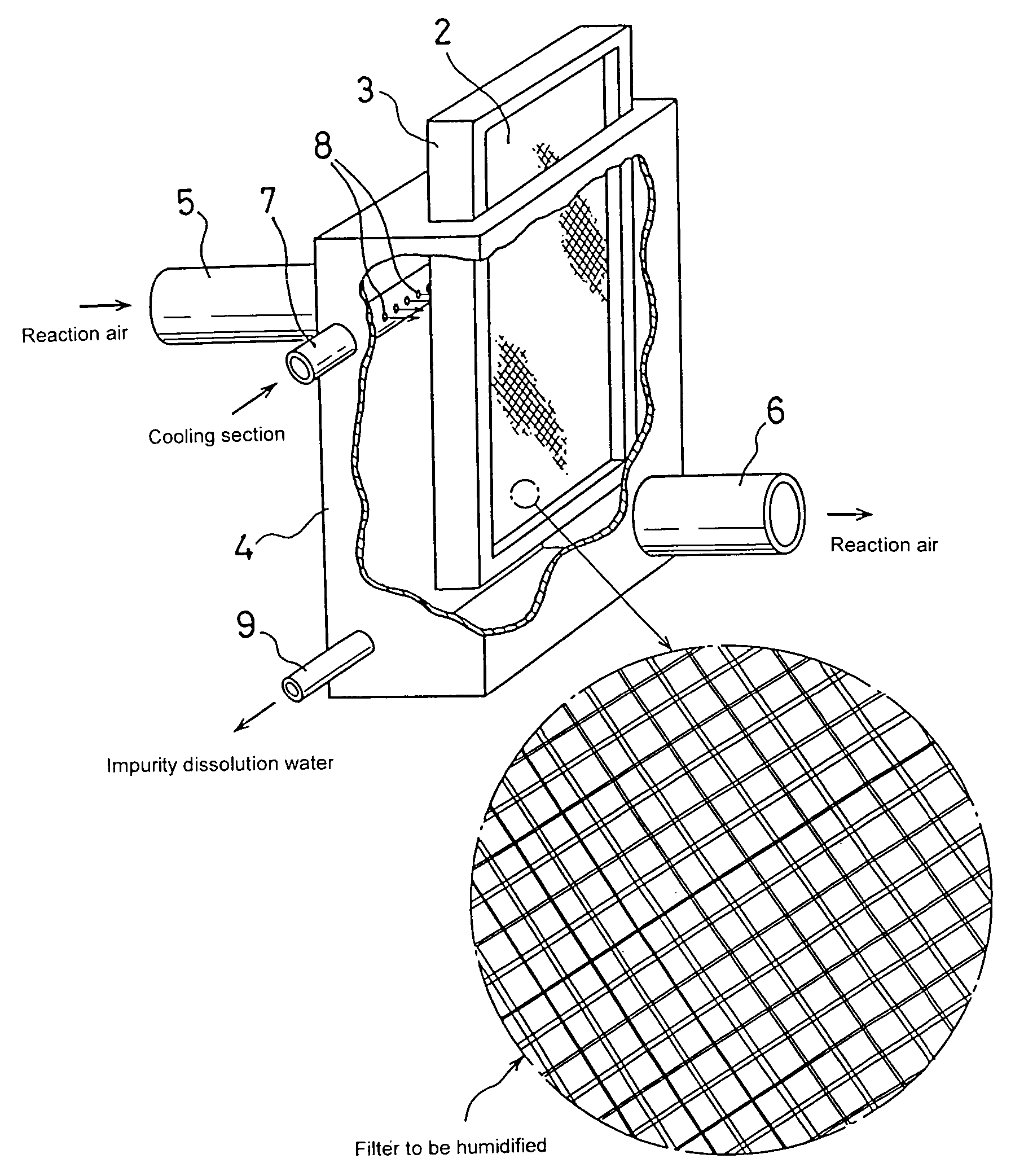
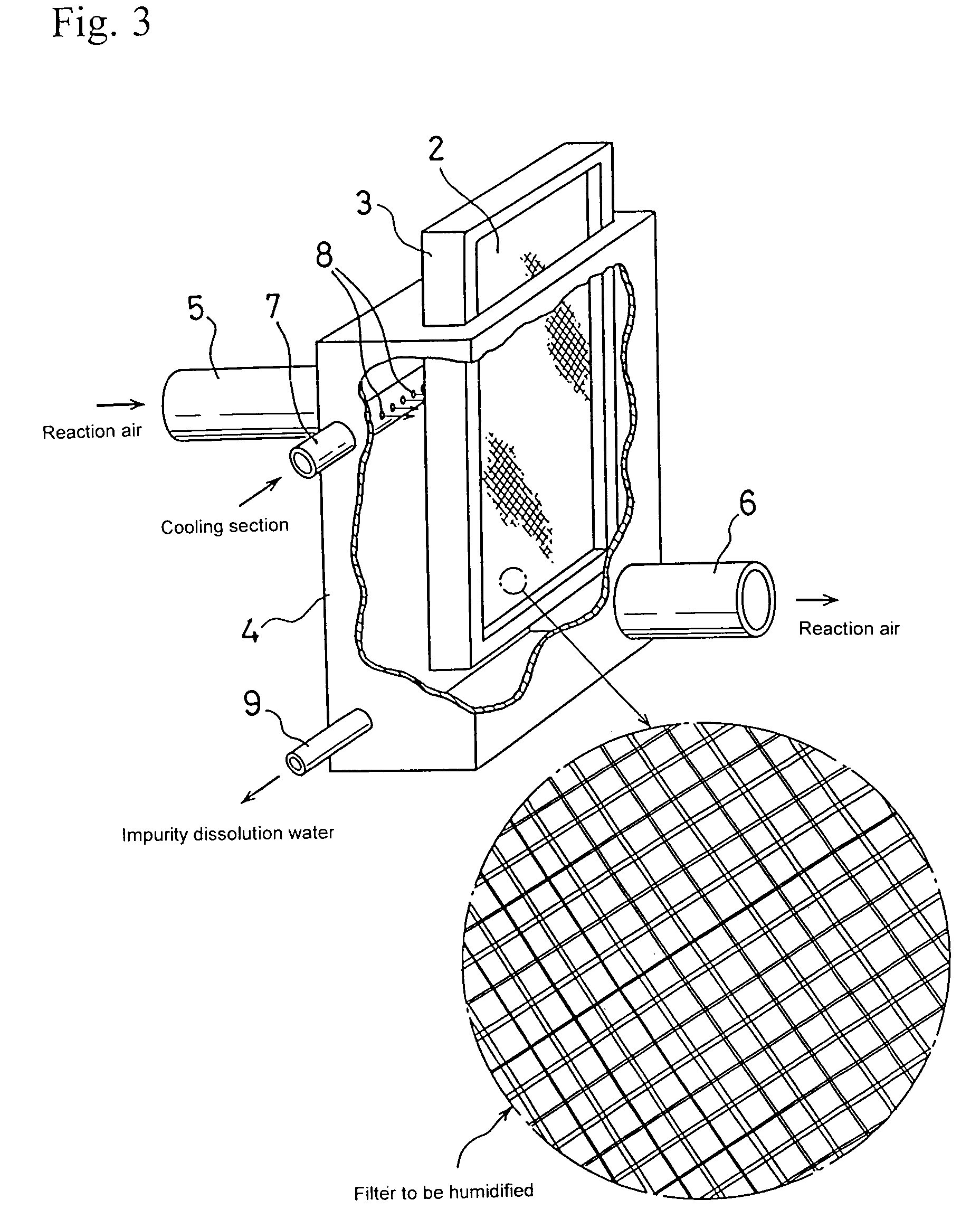
[0029]Said humidification filter 2 is composed of a sheet shape porous material presenting water absorption or hydrophilic property and, for instance, kept upright in a housing 4 by attaching a frame 3 around it as shown in FIG. 3. In this case, the filter body composed of sheet shape porous material has a single layer structure; however, it is possible to have a multilayer structure disposing 2 layers or more with an appropriate distance.

[0030]Said housing 4 is provided with an air inlet pipe 5 of reaction air at the back side, and this ...


PUM

PropertyMeasurementUnit
hydrophilic propertyaaaaaaaaaa
distanceaaaaaaaaaa
electric conductionaaaaaaaaaa

Abstract

The fuel cell power generation system of present invention can supply the air pole of a fuel cell with a clean air free from impurities, by providing at least one or more humidification filters kept in a wet state by a water supply means, disposed in an oxidant gas supply passage of the fuel cell body. As a result, the cell output properties can be improved by preventing the decrease of gas dissipation ability or the decrease of electric conductance of the solid polymer film provoked by impurities.

Description

FIELD OF THE INVENTION[0001]The present invention relates to a fuel cell power generation system, using a fuel cell, and more particularly, to a fuel cell power generation system for preventing the output characteristics of the fuel cell from deteriorating, by eliminating easily and effectively fine dust, salt or other impurities contained in the air to be supplied to an air pole of the fuel cell, and at the same time, for preventing the electric conduction of a solid polymer member from lowering, by conveniently humidifying air supplied to the air pole.BACKGROUND ART[0002]The fuel cell is sometimes applied to the power generation system and, in the prior art, for example, a fuel cell power generation system as shown in FIG. 6 has been developed. This fuel cell power generation system S comprises a fuel cell body A made of stacked body of unit cells, a fuel processing apparatus C modifying pure hydrogen or hydrocarbon base fuel B into hydrogen rich gas and supplying to a fuel cell b...

Claims


Application Information

Patent Timeline
Patent Type & Authority Patents(United States)
IPC IPC(8): H01M8/04H01M8/10H01M8/06
CPCH01M8/04119H01M8/04126H01M8/04164H01M8/0662H01M8/0687Y02E60/50H01M8/04H01M8/06
Inventor HATAYAMA, TATSUJIHAMADA, AKIRA
Owner SANYO ELECTRIC CO LTD
Why Eureka
Try Eureka