
Phase-shifting system using a displaceable dielectric and phase array antenna comprising such a phase-shifting system

a phase-shifting system and dielectric technology, applied in waveguides, delay lines, antennas, etc., can solve the problems of increasing mounting complexity, increasing susceptibility to faults, and adjusting and altering such mechanical down tilts with considerable complexity, so as to achieve the desired functionality and simplify the design

Inactive Publication Date: 2007-09-25
HUBERSUHNER AG
View PDF14 Cites 6 Cited by
  • Summary
  • Abstract
  • Description
  • Claims
  • Application Information

AI Technical Summary

Benefits of technology

[0011]The present invention is a phase shifter arrangement that avoids the disadvantages of the known phase shifter arrangements, such that the design is simplified and the desired functionality is reliably achieved, as well as an antenna array having such a phase shifter arrangement.
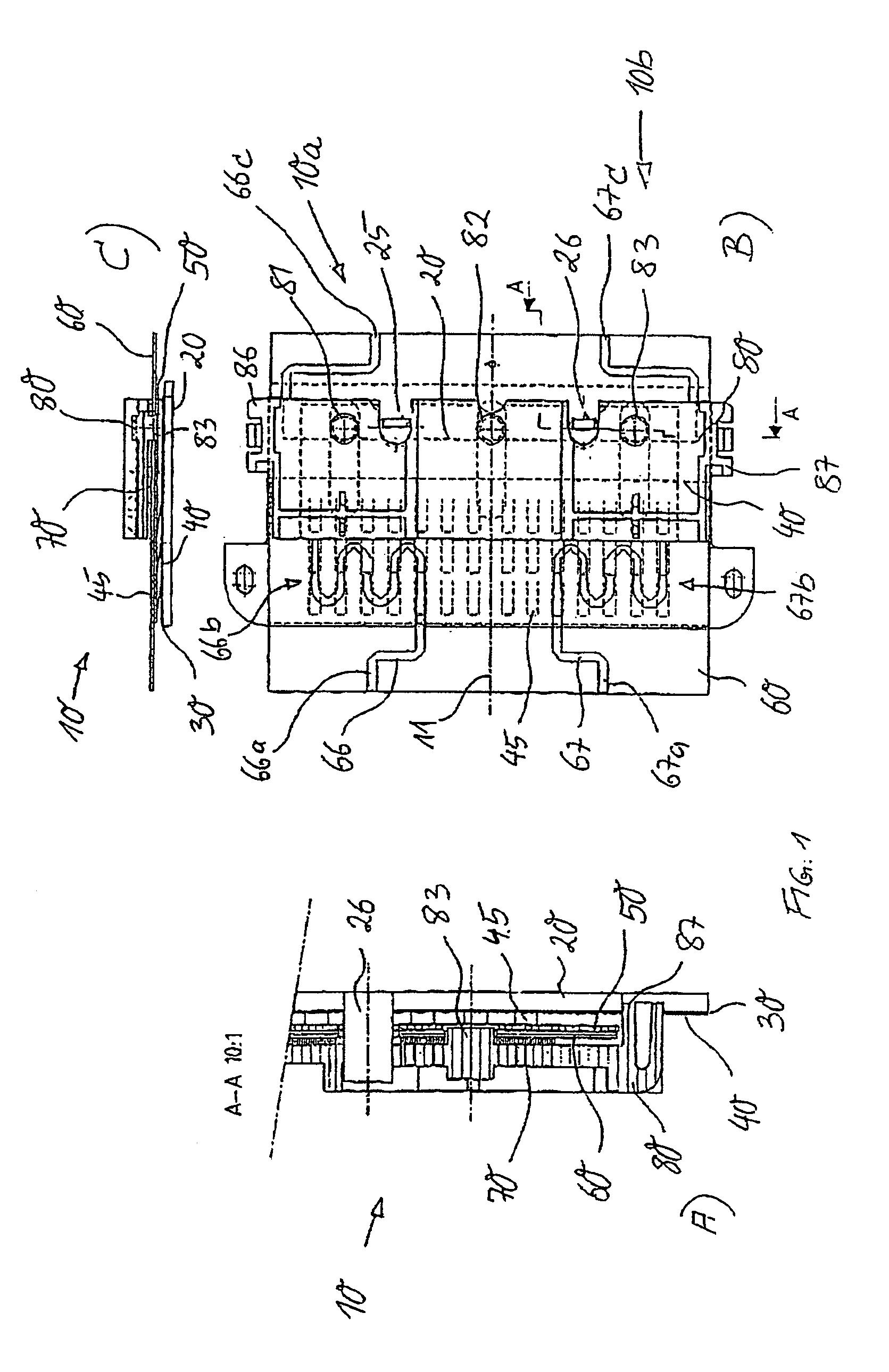
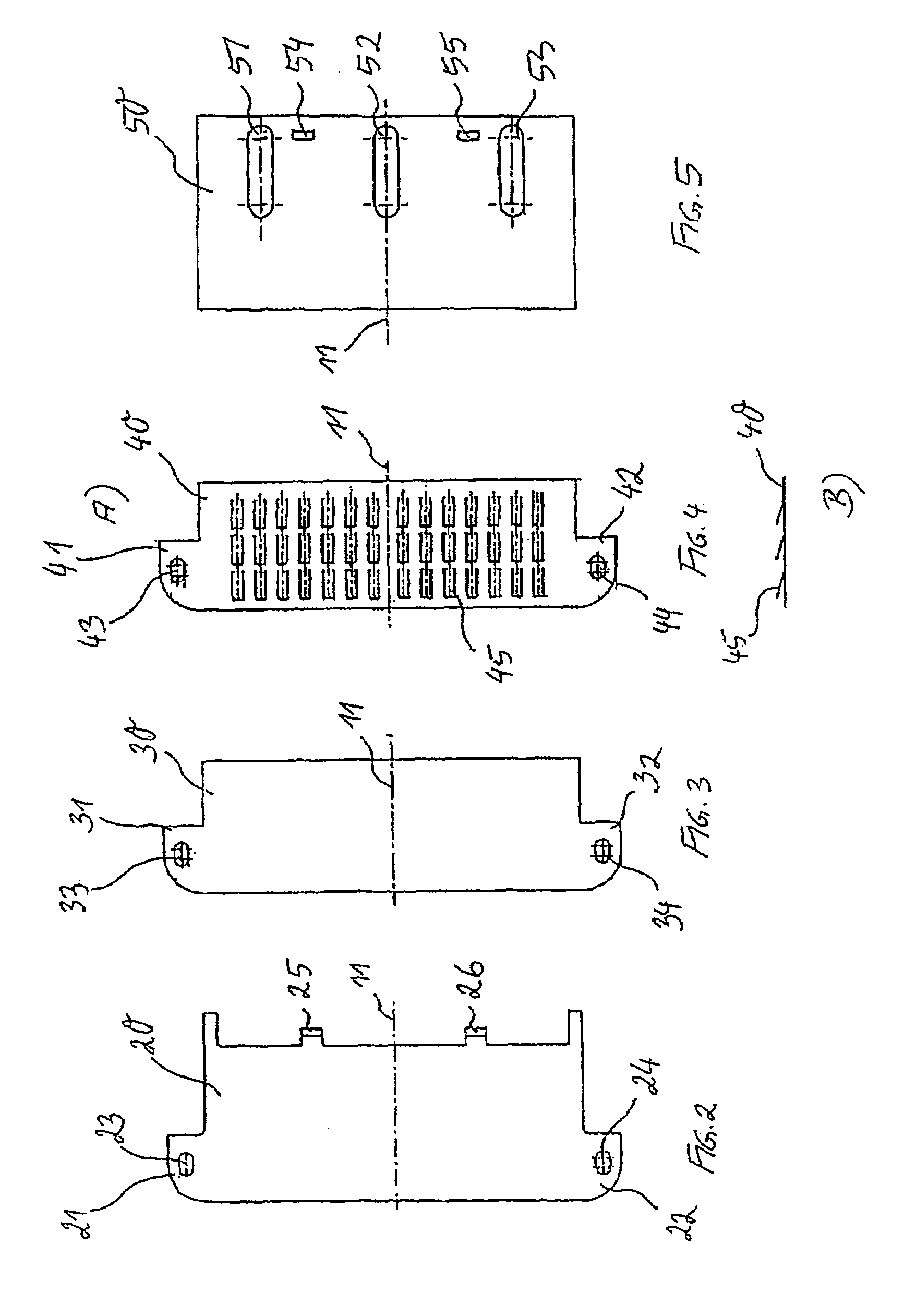
[0020]The phase shifter arrangement according to the invention is simplified further if the microstrip lines of the two phase shifters are arranged and formed on a common printed circuit board. Together with the common, displaceable dielectric, there is thus a high degree of synchronization with, at the same time, a particularly simple design.
[0022]In order for the displaceable dielectric to always be in a defined position relative to the microstrip lines below, it is advantageous if the microstrip lines of the two phase shifters and the common dielectric above are pressed flat against one another by means of a spring metal sheet.
[0024]Provided for the drive of the phase shifter is preferably a slide which is guided displaceably in the longitudinal direction, can be actuated manually from the outside or using a motor, and is in engagement with the dielectric. This configuration is particularly simple and functionally reliable and has the advantage of retaining its position when the motor drive fails.

Problems solved by technology

One disadvantage of this is the fact that considerable complexity is required to adjust and alter such a mechanical down tilt and it is usually necessary to climb the mast for this purpose.
Disadvantages of this known phase shifter arrangement are not only the complex displacement mechanism comprising a plurality of individual elements, but also the separate structure of the individual phase shifters which requires high accuracy on assembly and thus increased mounting complexity with, at the same time, increased susceptibility to faults.

Method used


Image

  • Phase-shifting system using a displaceable dielectric and phase array antenna comprising such a phase-shifting system
  • Phase-shifting system using a displaceable dielectric and phase array antenna comprising such a phase-shifting system
  • Phase-shifting system using a displaceable dielectric and phase array antenna comprising such a phase-shifting system

Examples


Embodiment Construction

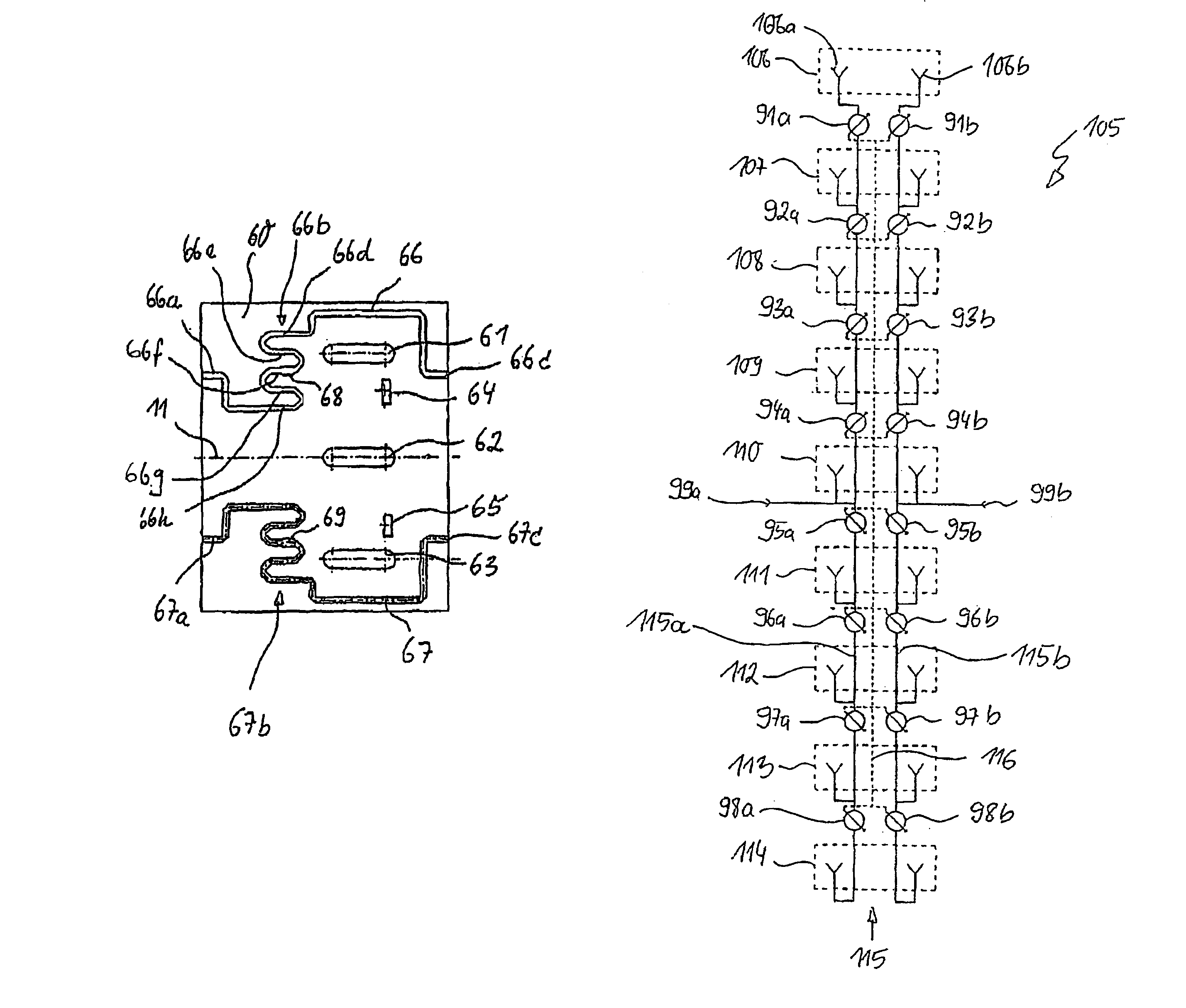
[0039]FIG. 10 shows the simplified circuit diagram of an antenna array 105, in which the present invention can advantageously be used. The antenna array comprises in total 9 radiators 106, . . . , 114, which are arranged one behind the other (one on top of the other) in a (vertical) mounting direction. Each of the radiators 106, . . . , 114 comprises two individual radiator elements 106a, b (the reference numerals for the radiator elements in the radiators 107, . . . , 114 are omitted for clarity). Each of the radiator elements 106a, b is associated with one polarization direction. The two polarization directions are generally at right angles to one another and usually form an angle of 45° with the mounting direction of the antenna array 105. The radiators 106, . . . , 114 are provided both for emitting and receiving radio waves.

[0040]The radiators 106, . . . , 114 or radiator elements 106a, b are connected, via a supply network 115, to two supply inputs 99a, b, which are arranged w...


PUM


Abstract

A phase-shifting system for electrically swiveling the direction of a beam of an antenna field includes several radiators with two planes of polarization. The phase-shifting system includes two jointly changeable phase shifters with microstrip lines associated therewith. The electrical length of each phase shifter can be changed by a dielectric which is slidable above the microstrip lines. Such a phase-shifting system offers a simplified design and added functional safety by arranging the microstrip lines of both phase shifters in parallel next to each other and by providing a common slidable dielectric in order to change the electrical length of the microstrip lines of both phase shifters.

Description

BACKGROUND OF THE INVENTION[0001]1. Field of the Invention[0002]The present invention relates to the field of radiofrequency engineering. It relates to a phase shifter arrangement and an antenna array having such a phase shifter arrangement.[0003]2. Description of Related Art[0004]In mobile radio technology, antenna arrays or antennas, in which two or more individual radiators are arranged one behind the other in a mounting direction and are driven via a common supply network, have long been known for equipping the base stations. In order to be able to take better account of the different conditions at the location of the respective base station and of the interaction with other base stations, it has proved to be advantageous to provide the antennas with the possibility of a “down tilt”. This may take place, in principle, by purely mechanical means by the antenna being designed such that it can be adjusted at the point at which it is fixed to the mast. One disadvantage of this is th...

Claims


Application Information

Patent Timeline
Patent Type & Authority Patents(United States)
IPC IPC(8): H01Q3/32H01P1/18H01Q3/30H01Q21/06
CPCH01P1/184H01Q3/30H01Q21/061
Inventor HEINIGER, MARKUSSPIRIG, EUGEN
Owner HUBERSUHNER AG
Learn More