Scanning optical apparatus and image forming apparatus using the same

a technology of optical apparatus and scanning optical apparatus, which is applied in the direction of measuring devices, instruments, printing, etc., can solve the problems of image writing light flux blocked, image quality deterioration, and image writing streaks

Inactive Publication Date: 2007-09-25
CANON KK
View PDF8 Cites 8 Cited by
  • Summary
  • Abstract
  • Description
  • Claims
  • Application Information

AI Technical Summary

Benefits of technology

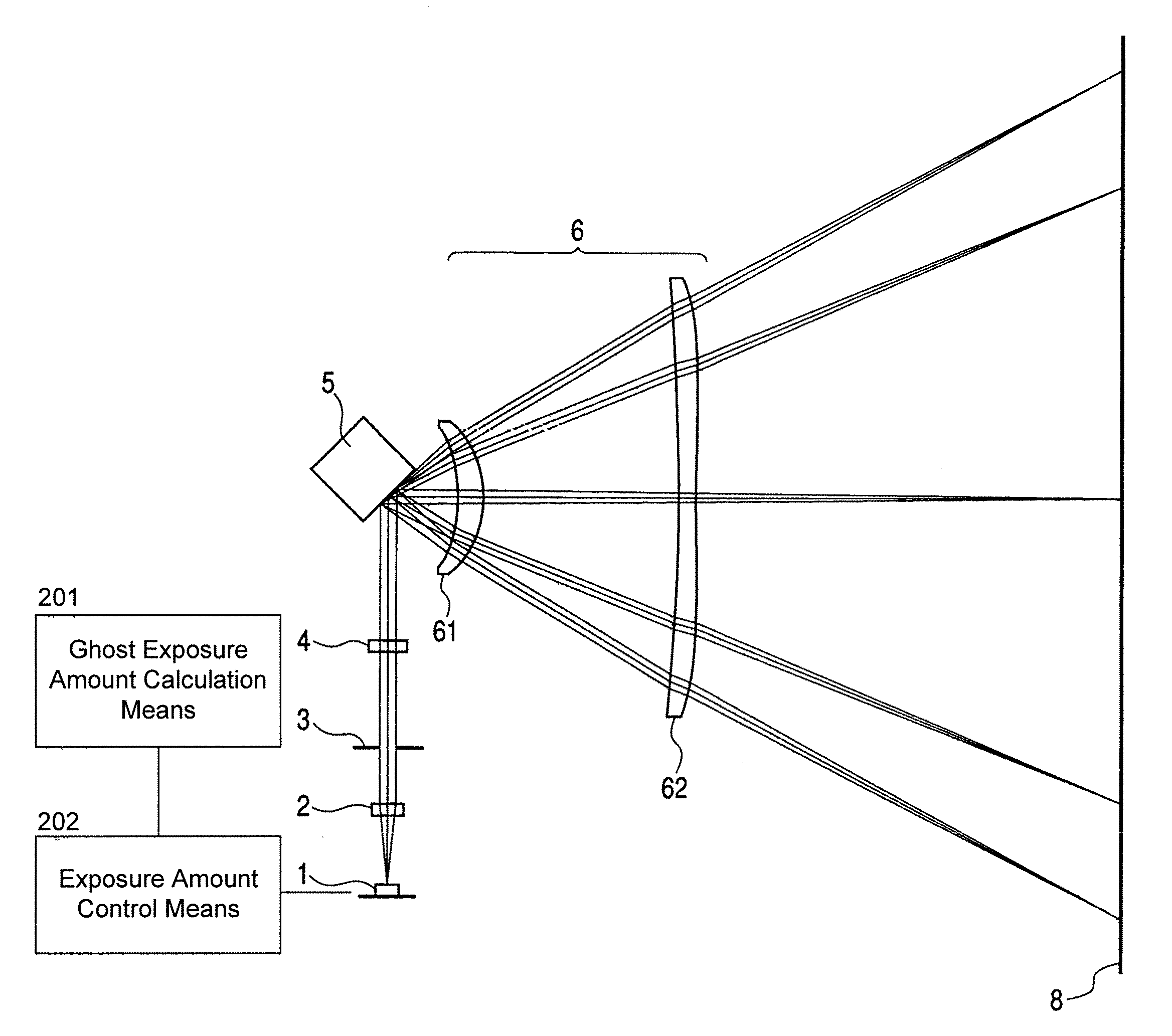
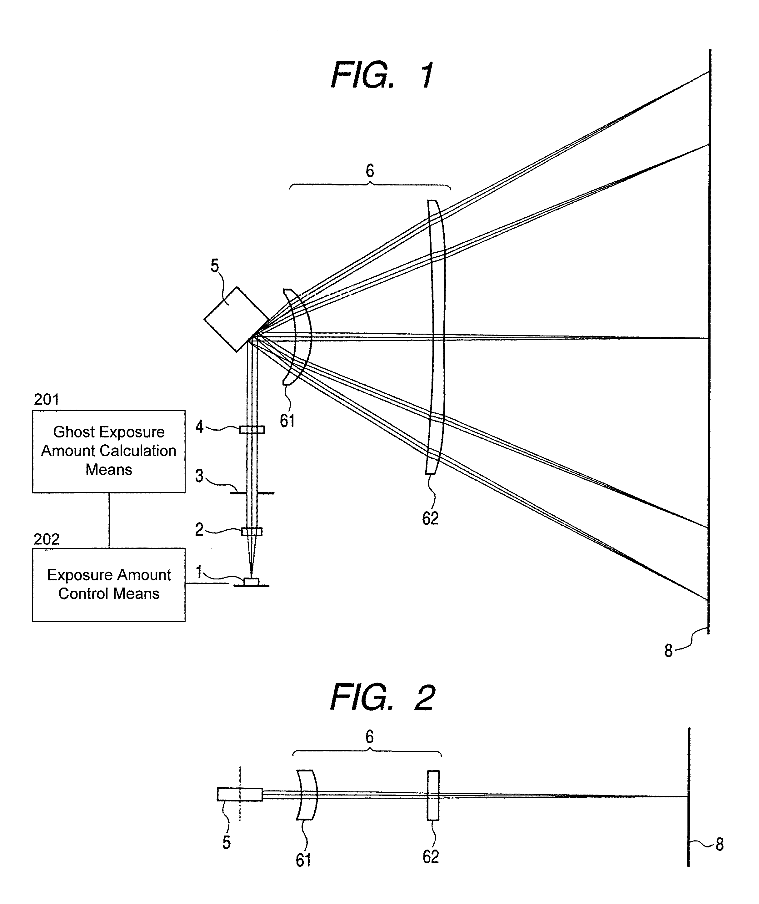
[0014]The present invention is intended to overcome or reduce the above-described problems. According to the present invention, a position at which ghost light is generated and its exposure amount are calculated based on an image signal with which printing is actually carried out and the light quantity and / or pulse width of an image writing light flux is controlled thereby correcting influence of ghost light electrically. With this feature, illumination distribution on the image plane on a surface to be scanned is made uniform. Thus, the present invention provides a scanning optical apparatus suitable for highly fine printing and an image forming apparatus using such a scanning optical apparatus.

Problems solved by technology

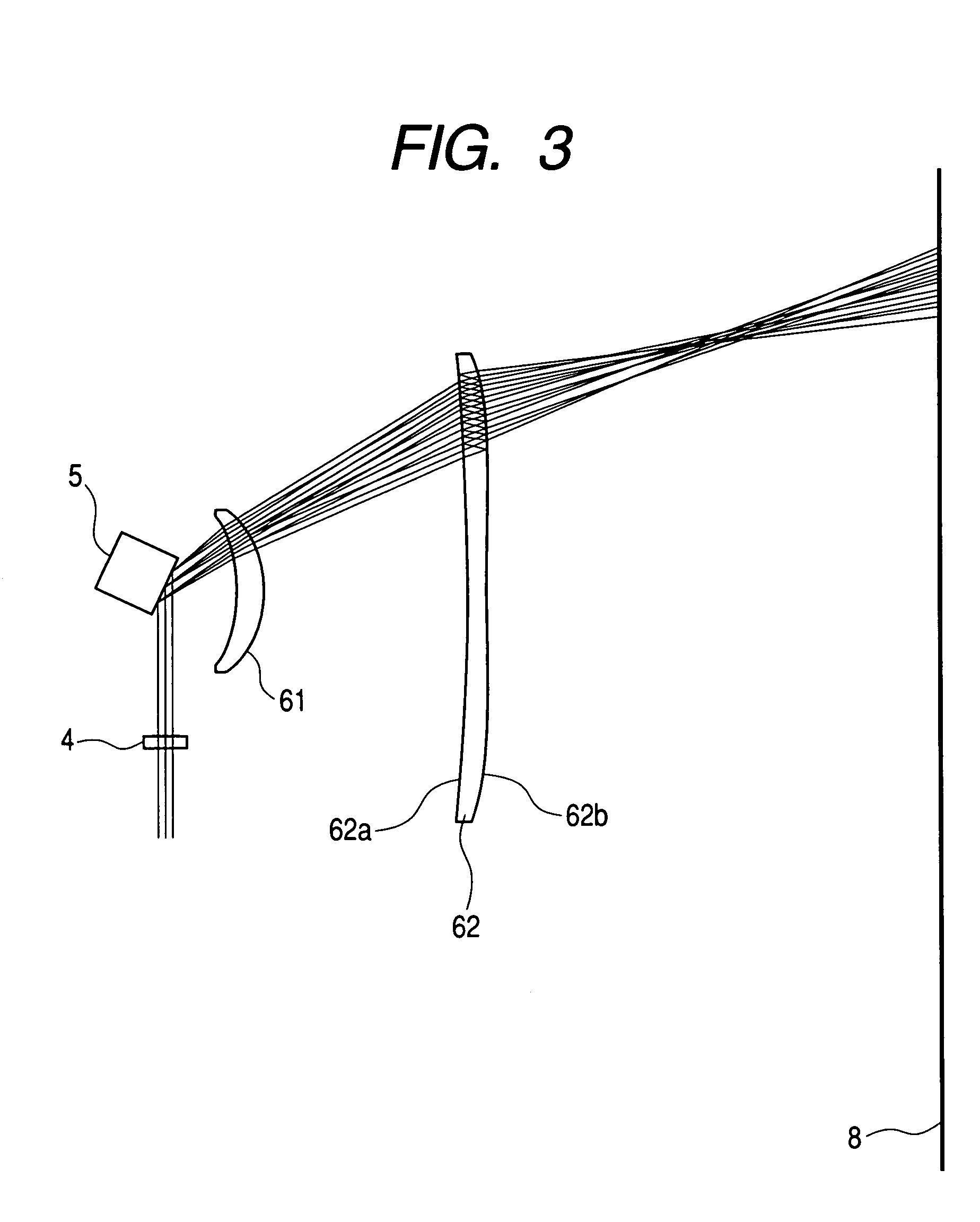
Conventionally, in the scanning optical apparatus and the image forming apparatus using the same, there has been a problem that deterioration of image quality such as streaks in an image of doubled images occurs on account of ghost light generated from optical elements or mechanical elements in the scanning optical apparatus.
The tandem type color image forming apparatus is equipped with a scanning optical system that scans light fluxes in the opposite directions by a common deflecting device, and it suffers from a problem that generated ghost light can be incident on the opposite surface to be scanned to cause streaks in images or misregistration of colors.
(1) blocking the ghost light with a mechanical member (disclosed in Japanese Patent Application Laid-Open No.
(2) separating the ghost light utilizing eccentricity of an optical element (disclosed in Japanese Patent No. 3365869); or
(3) guiding the ghost light outside the effective image area (disclosed in Japanese Patent Application Laid-Open No. 2001-305459) However, (1) in the case that the ghost light is blocked by a mechanical member, requirement for precision in position of the mechanical member is strict and there is a risk that an image writing light flux is also blocked in some cases, (2) in the case that the ghost light is separated by eccentricity of an optical element, aberrations of the optical system are deteriorated by the eccentricity and curvature of scanning line and rotation in the spot shape are caused, and (3) the optical design in which the ghost light is guided outside the effective image will reduce freedom in design and the structure will be complicated. In addition, with any one of the above measures, there remains ghost light that cannot be eliminated completely depending on the shape of optical elements, for example, ghost light generated by internal reflection.

Method used


Image

  • Scanning optical apparatus and image forming apparatus using the same
  • Scanning optical apparatus and image forming apparatus using the same
  • Scanning optical apparatus and image forming apparatus using the same

Examples


second embodiment

[0099]FIG. 6 is a cross sectional view in the main scanning direction showing a scanning optical apparatus according to a second embodiment of the present invention. FIG. 7 is a cross sectional view in the sub scanning direction. What is different in the second embodiment from the first embodiment is that the scanning optical apparatus is a tandem type scanning optical apparatus in which a plurality of different surfaces to be scanned are scanned by a plurality of light fluxes simultaneously, that the scanning optical apparatus is equipped in a color image forming apparatus, and that ghost light that travels from an optical element to the opposite surface to be scanned is electrically corrected accordingly. The other features than mentioned above are the same as the first embodiment.

[0100]The apparatus according to this embodiment is a scanning optical apparatus provided with two scanning optical systems 6 opposed to each other with a deflecting element 5 between and one more simila...

third embodiment

[0115]What is different in the third embodiment from the first embodiment is that the calculated exposure amount by ghost light is corrected by controlling the pulse width of the light source. The other features than mentioned above are the same as the first embodiment.

[0116]In this embodiment, the pulse width (i.e. time) of the light emitted from a light source is controlled, instead of the emitted light quantity of the light source, based on the ghost exposure amount calculated in FIG. 5B. More specifically, the pulse width of the emitted light is made short at the position at which ghost appears by an amount corresponding to the ghost exposure amount to make the image surface illuminance on the surface to be scanned uniform.

[0117]In other words, the emitted light pulse width (time) of a regular image writing light flux in the area in which the exposure amount of ghost light is large is made smaller than the emitted light pulse width of a regular image writing light flux in the ar...


PUM


Abstract

An object of the present invention is to prevent deterioration of image quality caused by ghost light generated from components of a scanning optical apparatus. In the present invention, an image writing light flux is related with a position at which ghost light appears and the exposure amount of the ghost light and a ghost light exposure amount on a surface to be scanned is calculated on comparison with an actual image signal, and the light quantity or the pulse width of a light flux emitted from a light source is controlled based on the calculated ghost light exposure amount.

Description

BACKGROUND OF THE INVENTION[0001]1. Field of the Invention[0002]The present invention relates to a scanning optical apparatus, and particularly to an scanning optical apparatus suitable for an apparatus, such as a laser beam printer using an electrophotography process or a digital copying machine, in which a light flux emitted form light source means is deflected by a deflecting element to scan a surface to be scanned with light via an imaging element having fθ characteristics so as to record image information. The present invention also relates to an image forming apparatus using such a scanning optical apparatus.[0003]2. Related Background Art[0004]In conventional scanning optical apparatuses such as a laser beam printer (LBP), a light flux emitted from light source means is optically modulated in accordance with an image signal. The light flux thus optically modulated is periodically deflected by a light deflecting device composed of a polygon mirror and focused by an imaging opt...

Claims


Application Information

Patent Timeline
Patent Type & Authority Patents(United States)
IPC IPC(8): G02B26/08B41J27/00B41J2/44G02B26/10G02B26/12
CPCG02B26/127
Inventor KATO, MANABU
Owner CANON KK
Why Eureka
Try Eureka