
Protection system and method for resilient packet ring (RPR) interconnection

a protection system and resilient technology, applied in the field of systems and methods of failure protection between interconnected rprs, can solve problems such as the inability to deliver inter-ring messages, and achieve the effect of fast protection mechanisms

Active Publication Date: 2007-09-25
RPX CORP +1
View PDF5 Cites 21 Cited by
  • Summary
  • Abstract
  • Description
  • Claims
  • Application Information

AI Technical Summary

Benefits of technology

[0015]The present invention overcomes the problem of large convergence times, typically in the order of seconds in existing art, by offering faster protection mechanisms that achieve protection switching in shorter period of time. In the present invention a protection switching is completed in less than 50 ms in interconnected RPRs.

Problems solved by technology

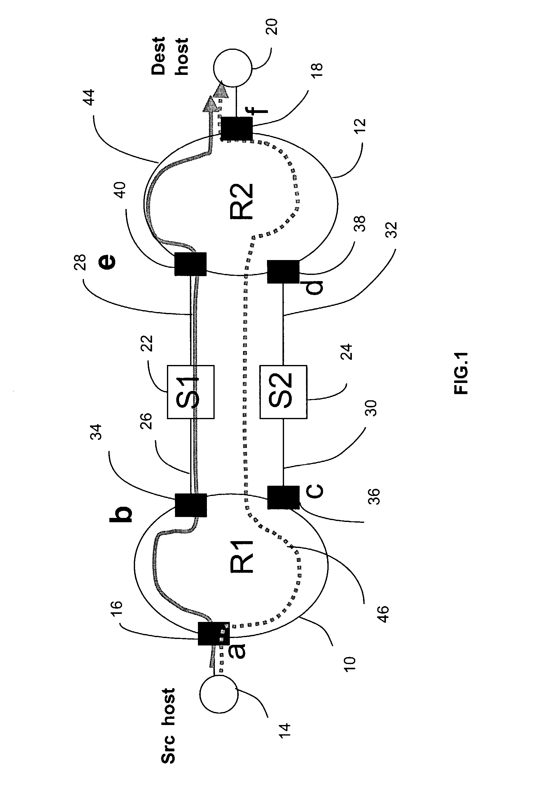
Using a single bridge or router between two interconnected rings leads to a single point of failure: if the interconnection device fails, an inter-ring message cannot be delivered.

Method used


Image

  • Protection system and method for resilient packet ring (RPR) interconnection
  • Protection system and method for resilient packet ring (RPR) interconnection
  • Protection system and method for resilient packet ring (RPR) interconnection

Examples


first embodiment

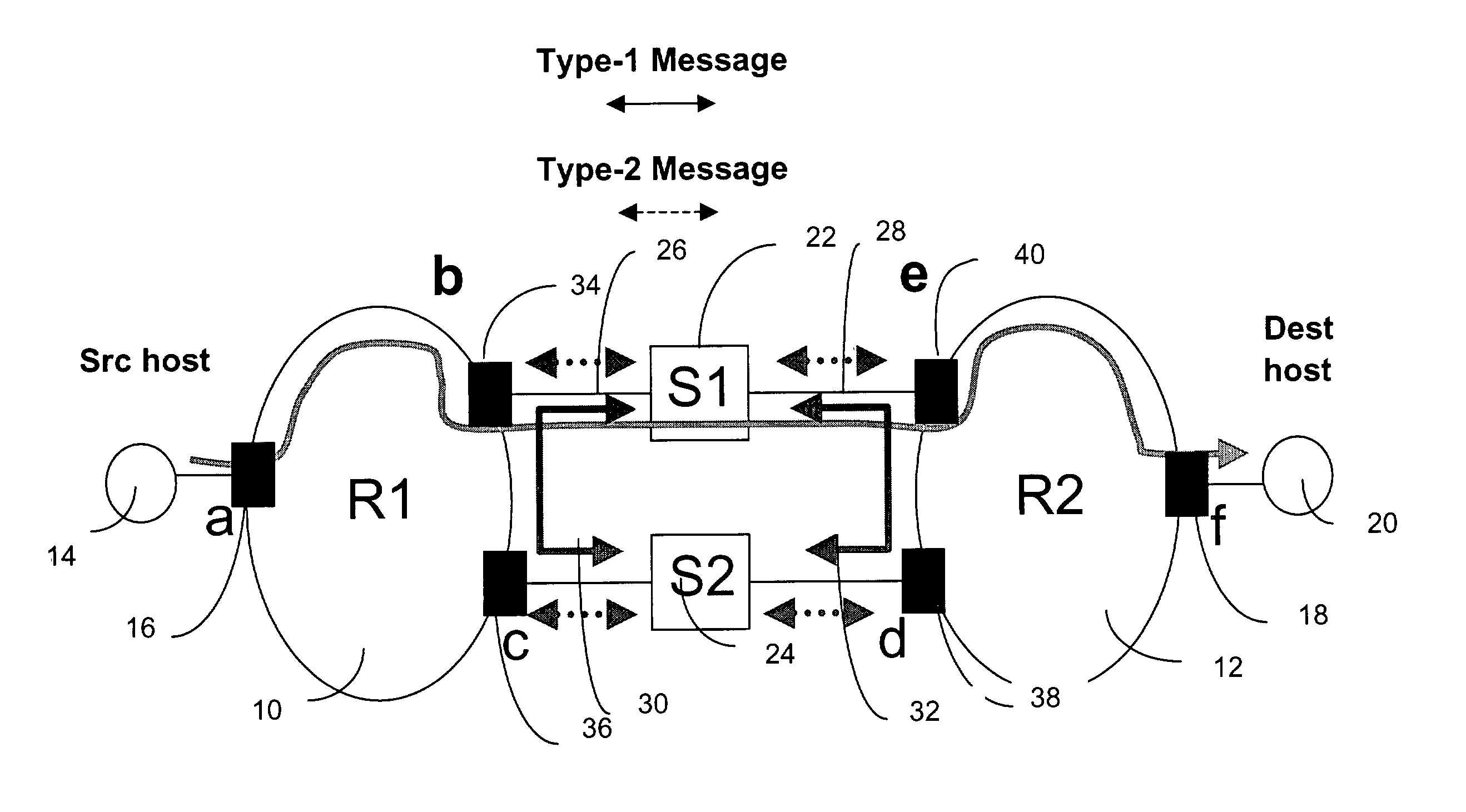
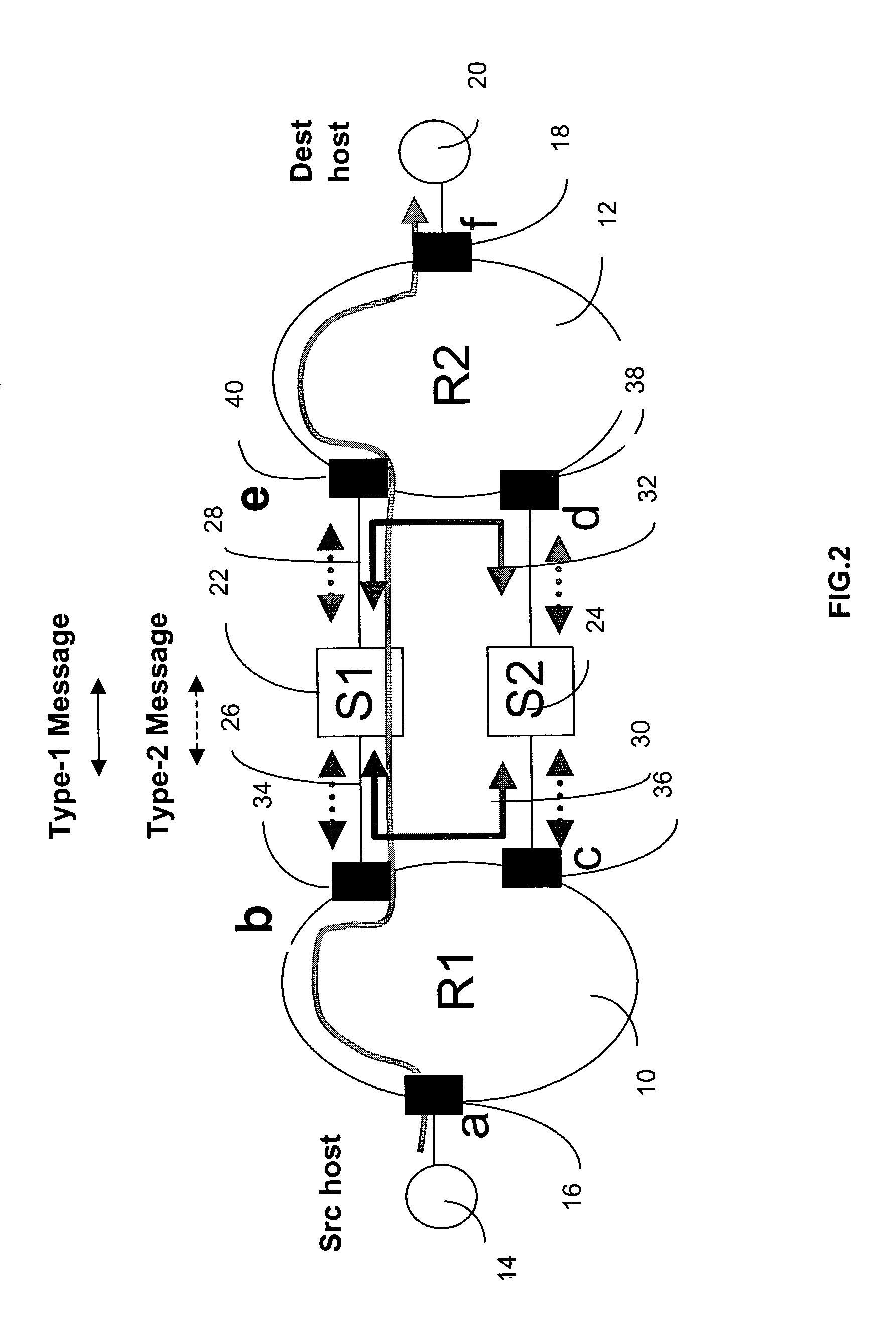
[0031]The control message based failure detection method used in the first embodiment is presented in FIG. 2. There are two components of the protection method: failure detection and failure notification. Failure detection is achieved by using periodic “keep-alive” messages that are exchanged between nodes. A keep-alive message is a short control message between two nodes, for example “x” and “y”. The reception of a keep-alive message from “y” at “x” indicates that “y” as well, as all the nodes and links in the interconnection path between “x” and “y” are alive (free from failure). The viability of such keep-alive messages is well known in various distributed processing contexts and is deployed in the novel protection method provided by this invention. Two types of keep-alive messages are used in the invention.

[0032]Type-1 messages are sent by each interconnection device S122 or S224 to the other with a period T1. T1 is programmable, with 10 ms being a typical value. The Type-2 mess...

second embodiment

[0047]In the protection system (shown in FIG. 12), the interconnection between the rings is performed through a set of dual interconnection units (42 and 48), each of which includes an interconnection device, two RPR interface nodes, and the corresponding interconnection links. For example, “interconnection unit-1”42 contains the first RPR interface node “b”34, the first interconnection device S122, and the fourth RPR interface node “e”40; whereas, the “interconnection unit-2”48 includes the second RPR interface node “c”36, the second interconnection device S224 and the third RPR interface node “d”38 (see FIG. 11). The first and the fourth interconnection links 26 and 28 are used to interconnect the first RPR interface node “b”34 and the fourth RPR interface node “e”40 with the first interconnection device S122. The second and the third interconnection links 30 and 32 are used for connecting the second RPR interface node “c”36 and the third RPR interface node “d”38 with the second i...


PUM


Abstract

A failure protection between interconnected adjacent Resilient Packet Rings (RPRs) in a multiple RPR network is provided. Two paths, a regular message path and a protection path, are provided between two adjacent RPRs. The regular path is used for routing inter-ring messages when no failure has occurred on the path. Messages are rerouted through the protection path when a failure occurs on the regular path. Each of these paths has two RPR interface nodes (one for each RPR) that are connected to an interconnection device (a layer 2 bridge or a layer-3 router) through interconnection links. Procedures for detecting failures and generating notifications for message rerouting and fault reports are executed at the interconnection devices. The procedures use periodic keep alive messages for diagnosing network segment and interconnection device failures. The fault detection and message rerouting are accomplished in less than 50 ms.

Description

FIELD OF INVENTION[0001]The invention relates to systems and methods of failure protection between inter-connected RPRs.BACKGROUND OF THE INVENTION[0002]Resilient Packet Ring (RPR) is an effective solution for metropolitan area data transport applications. RPR is a Media Access Control (MAC) protocol that operates at Layer-2 of the OSI (Open System Interconnection) protocol stack. RPR provides a ring topology for interconnection among nodes that exchange data with one another. It provides a packet ADM (Add-Drop Multiplexer) architecture and is compatible with Ethernet, SONET (Synchronous Optical NETwork), or DWDM (Dense Wavelength Division Multiplexing) physical layer standards. RPR has a number of characteristics that are responsible for its popularity and are briefly described in a white paper by the RPR Alliance “An Introduction to Resilient Packet Ring Technology”, by Gunnes Aybay, Mannix O'Connor, Kanaiya Vasani and Tim Wu, October 2001. RPR that employs a packet ring technolog...

Claims


Application Information

Patent Timeline
IPC IPC(8): G01R31/08H04J3/08H04L12/437H04L12/56H04L69/40
CPCH04J3/085H04L45/00H04L45/22
Inventor LEE, BYOUNG-JOONBACQUE, JAMES BENSON
Owner RPX CORP
Learn More