Method of measuring discrete, incremental feedback from motion devices

Inactive Publication Date: 2007-09-25
GOLDMAN CRAIG E
View PDF1 Cites 0 Cited by
  • Summary
  • Abstract
  • Description
  • Claims
  • Application Information

AI Technical Summary

Benefits of technology

[0020]It may appear at first that the accuracy of both the traditional fixed sampling period method and the variable sampling period method according to the invention can be improved by lengthening the (minimum) sample period. However, in real motion systems, the motion is not maintained at a single velocity. Long sample periods average the data over the sampling period, resulting in loss of the fine details of the motion. Even in motion systems that attempt to maintain a fixed velocity over time, the actual motion produced by the system can vary considerably. Measuring the fine details of this motion is an important first step to improving the user's understanding of the system, and ultimately to improving the control of the motion.
[0021]One of the areas that can benefit significantly from the invention is multi-axis coordinated motion control. In a simple motion control system with coordinated motion, the movement of one axis, called the “slave axis”, is determined by a formula based on the measured movement of another axis, called the “master axis”. One of the main problems of coordinated motion is accurately determining the velocity of the maste

Problems solved by technology

Digital control systems using a microprocessor require a certain amount of time to calculate the resultant “error” value.
Quantization error occurs because the controller only accumulates discrete events.
The position error associated with this small amount of motion is negligible, but the short sampling period magnifies the effect of the unaccounted motion to create larger uncertainties in velocity and acceleration measurements.
The problem of properly recording less than one pulse per sample per

Method used


Image

  • Method of measuring discrete, incremental feedback from motion devices
  • Method of measuring discrete, incremental feedback from motion devices

Examples


Example

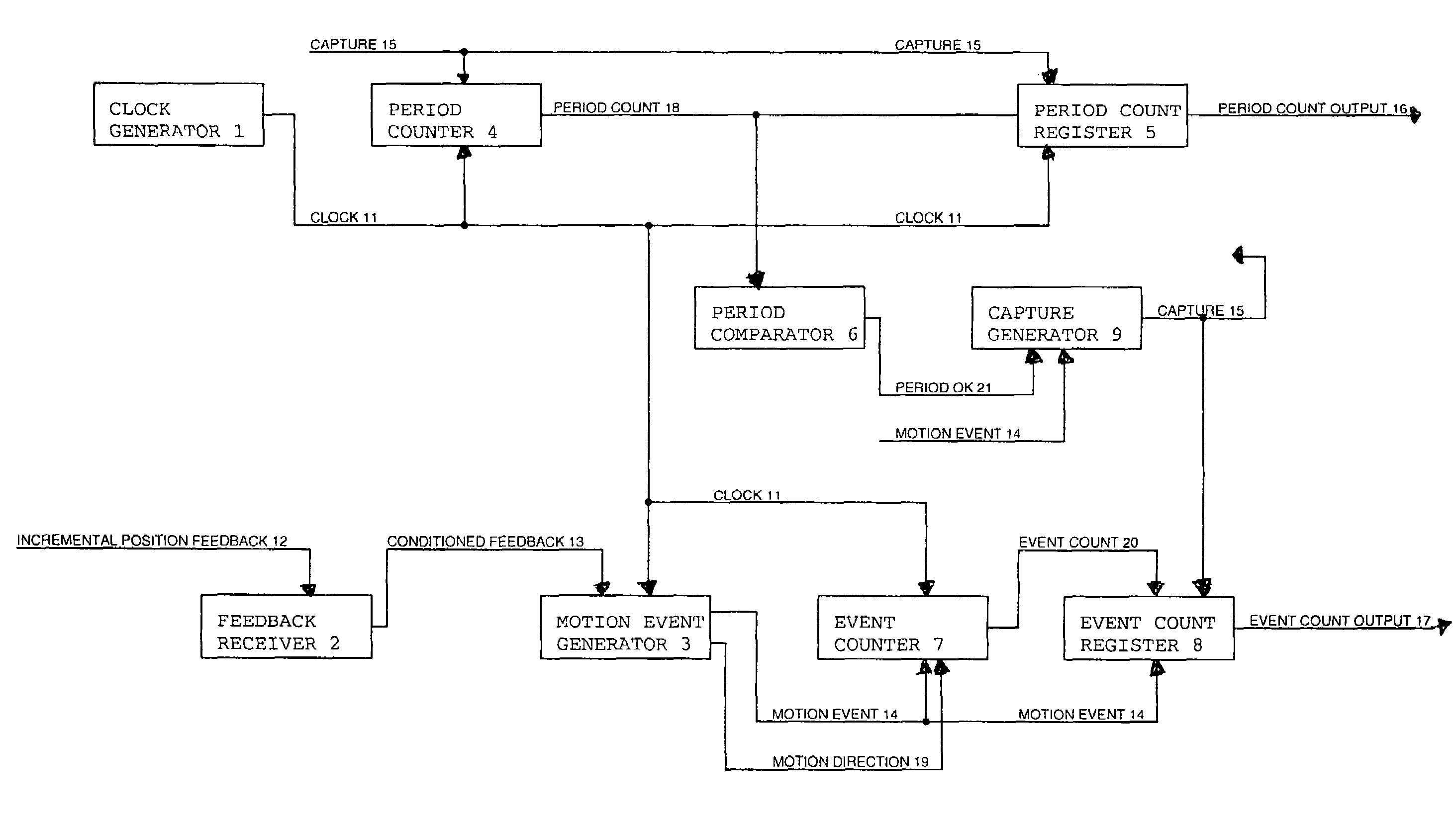
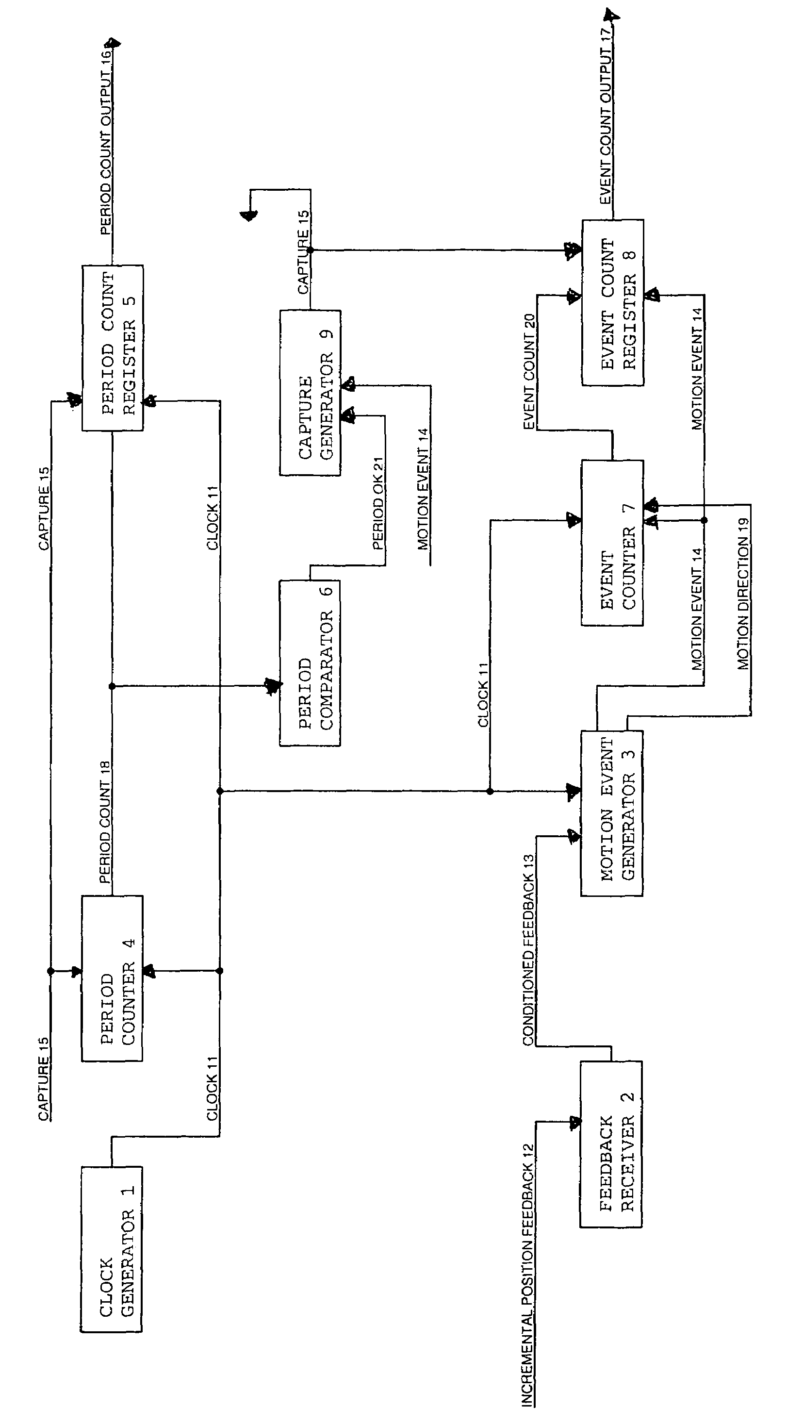
[0027]The invention may be accomplished with the system depicted in the figure. Clock Generator 1 produces Clock signal 11. There are also one or more Incremental Position Feedback signal(s) 12 received by Feedback Receiver 2. Feedback Receiver 2 provides electrical conditioning and transformation of the incoming feedback signal(s). The output of Feedback Receiver 2 is Conditioned Feedback signal(s) 13. Conditioned Feedback signal 13 and Clock signal 11 connect to Motion Event Generator 3. The output of Motion Event Generator 3 is Motion Event signal 14, which is a signal that has a single pulse for every occurrence of a motion event indicated by Feedback signal(s) 12. Motion Event Generator 3 also outputs Motion Direction signal 19.

[0028]Clock signal 11 and Capture signal 15 connect to Period Counter 4, which counts up on every incidence of Clock signal 11 and resets to zero on Capture signal 15. The output of Period Counter 4, Period Count signal 18, connects to Period Count Regis...


PUM


Abstract

A method of measuring discrete incremental feedback from motion systems that creates a discrete feedback pulse for every unit of motion that is accomplished by the motion system. The method comprises establishing a minimum feedback pulse sampling period, and accumulating feedback pulses during a sampling period. Upon the first feedback pulse after the minimum feedback pulse sampling period has passed, the current sampling period is ended, and the next sampling period is begun. The quantity of feedback pulses accumulated during the current sampling period is then determined.

Description

CROSS REFERENCE TO RELATED APPLICATION[0001]This application claims priority of Provisional application Ser. No. 60 / 404,673, filed on Aug. 20, 2002.FIELD OF THE INVENTION[0002]This invention relates to a method of measuring discrete, incremental feedback from motion devices.BACKGROUND OF THE INVENTION[0003]A typical motion system consists of four elements, a motion controller that directs the motion, a motion actuator, a driver unit that controls power applied to the motion actuator, and a feedback device that measures the motion and provides feedback to the controller. Two types of feedback are typically used—incremental and absolute. In a typical motion system, the motion controller provides a signal to the motor driver that causes the motor to turn. As the feedback device, the pulse encoder creates a discrete pulse for every unit of motion that occurs and sends this pulse back to the motion controller. This is referred to as a motion event. The motion controller accumulates these...

Claims


Application Information

Patent Timeline
IPC IPC(8): G01R25/00G06F19/00
CPCG05B19/401G05B2219/37139G05B2219/37143
Inventor GOLDMAN, CRAIG E.
Owner GOLDMAN CRAIG E
Why Eureka
Try Eureka