

Method for programming a multiple device control system using object sharing
a control system and object sharing technology, applied in the direction of program control, electric programme control, instruments, etc., can solve the problems of large cost of managing shared objects and reflecting changes on the system by manpower, low programming efficiency, etc., and achieve the effect of facilitating system building
- Summary
- Abstract
- Description
- Claims
- Application Information
AI Technical Summary
Benefits of technology
Problems solved by technology
Method used
Image

Examples
embodiment 1
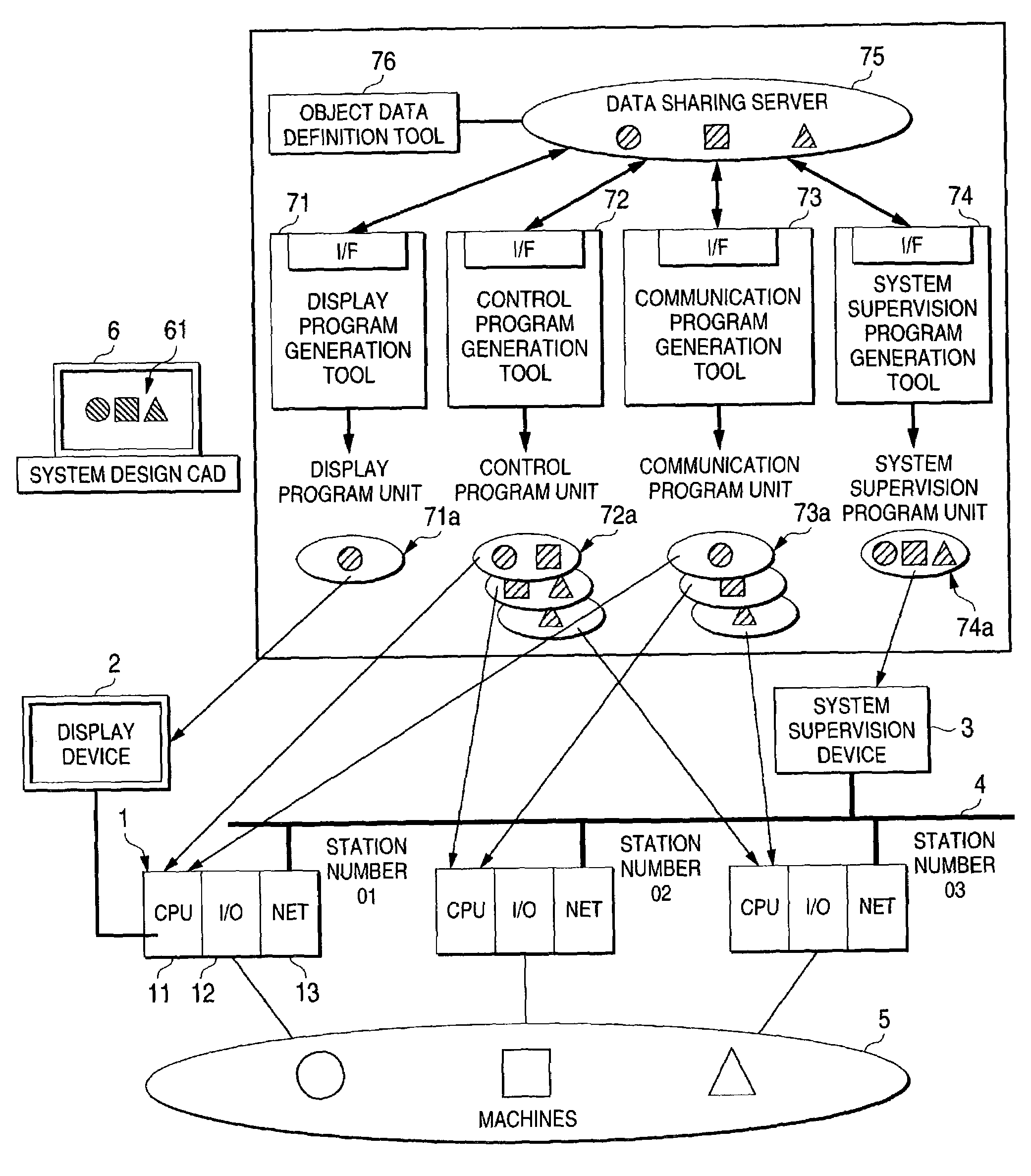
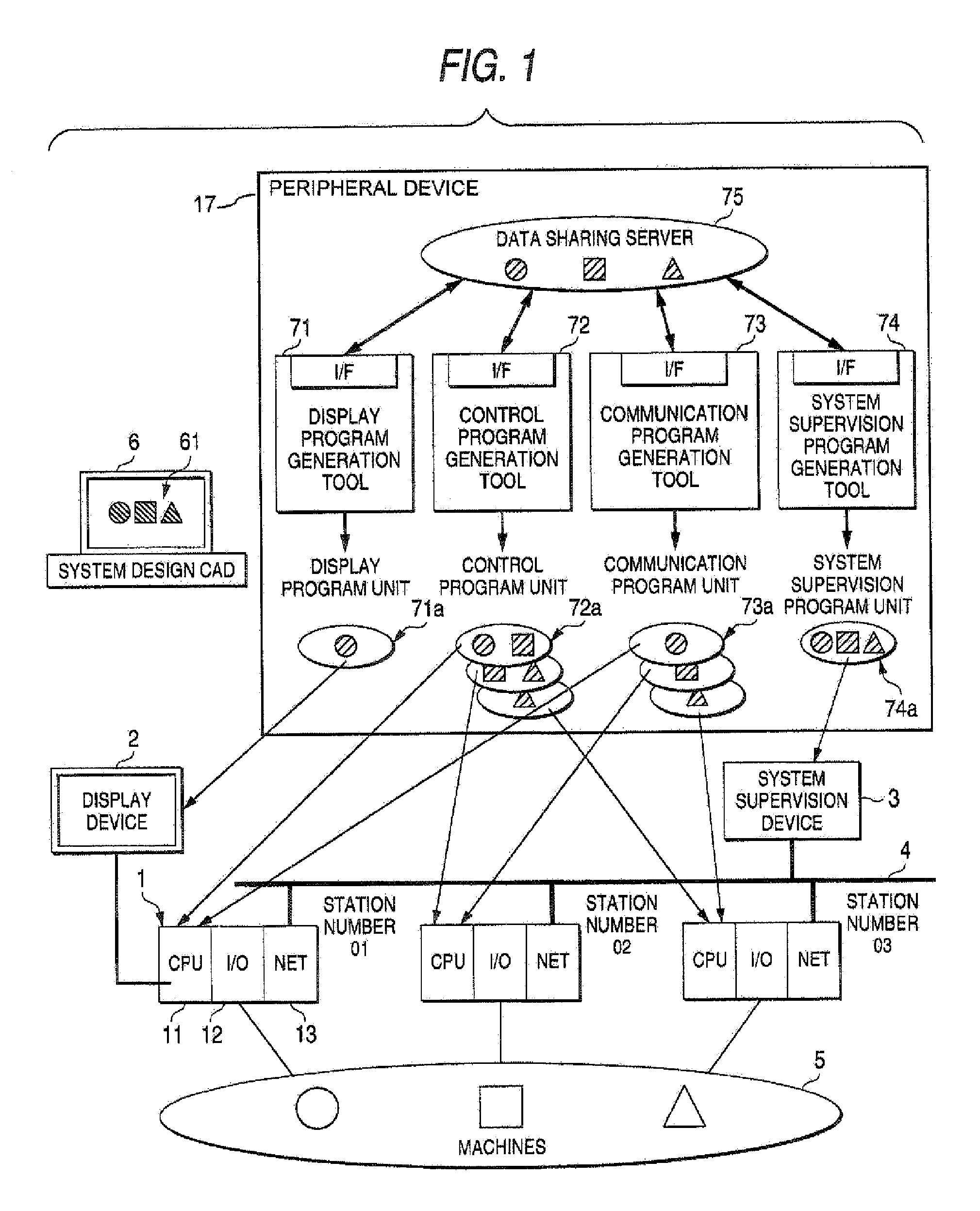
[0055]FIG. 1 is a status diagram showing an outline operation performed when generating and writing program units in a control system constructed of a programmable controller, a display device and a system supervision device, and represents a basic configuration of a data sharing programming device.
[0056]In the figure, reference numeral 1 represents a programmable controller which controls a group of machines 5 and performs communication via network by running a control program unit and a communication program unit; 2 a display device which downloads and runs a display program unit to display, for example, a state of the machines 5; 3 a system supervision device which runs a system supervision program unit to detect, for example, an abnormal condition in a production line and inform it to a worker at the production line; 4 a network for connecting the programmable controllers 1 and the system supervision device 3; 5 a group of machines controlled by the programmable controllers 1; 6...
embodiment 2
[0096]FIG. 4 shows a basic configuration of a data sharing programming device in which an object data definition tool 76 to define and change object data for the data sharing server 75 is added to the peripheral device 7 explained in the embodiment 1.
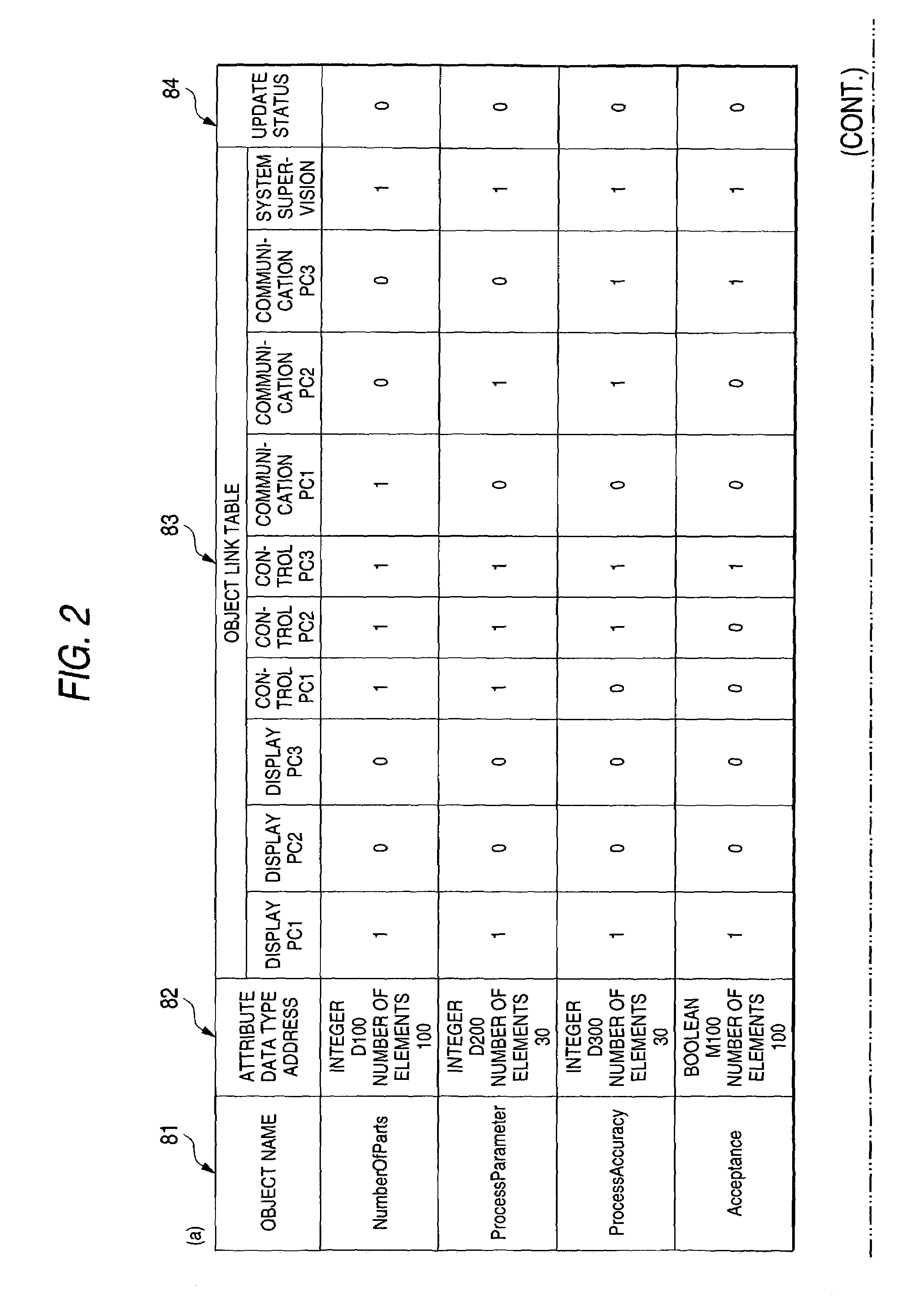
[0097]The content of the object management table according to the first embodiment is generated by the setting screen of the program generation tool and transferred through the interface unit built thereinto by performing connection of the circuit (Open command), addition, modification and deletion of an object (Add, Mod, Del), and disconnecting of the circuit (Close). In the object management table according to this embodiment, the definition and modification of the object can be done directly based on the object data definition tool and the defined or modified contents can also be reflected in the entire system through the server.
[0098]Next, the operation when the dedicated object data definition tool 76 is used will be explained by r...
embodiment 3
[0113]FIG. 6 shows a basic configuration of a data sharing programming device in which a system configuration tool 77 of the same configuration as the system design CAD 6 is added to the peripheral device 7 explained in the embodiment 2. The system configuration tool 77 selects an object to be actually used from among registered, highly useful controlled objects and change the definition according to the data of the selected object, the registered objects having been used in building previous systems and, after the completion of the systems, registered for future use in the building of other systems.
[0114]This embodiment concerns the operation when a part of an existing fundamental system is changed to construct an intended system. The operation using the system configuration tool 77 based on the system design CAD 6 will be described by referring to a flow chart of FIG. 7.
[0115]First, in step S21, in the system configuration tool 77 the user selects an object to be actually used fro...
PUM
 Abstract
Description
Claims
Application Information