Method and apparatus for venting a crankcase of an internal combustion engine

a crankcase and internal combustion engine technology, which is applied in the direction of crankcase ventillation, combustion engines, machines/engines, etc., can solve the problems of unnecessarily burdening the exhaust-gas catalytic converter, and achieve the effect of improving the oil quality and volumetric flow over the engine running tim

Active Publication Date: 2007-10-02
DAIMLER AG
View PDF17 Cites 24 Cited by
  • Summary
  • Abstract
  • Description
  • Claims
  • Application Information

AI Technical Summary

Benefits of technology

[0010]In this way, the first venting line, which is used to vent the crankcase during part-load operation of the internal combustion engine, is closed when the internal combustion engine is operating in the overrun mode. This prevents blow-by gases from passing via the intake system and the combustion chamber into the exhaust system and therefore to the exhaust-gas catalytic converter, where the hydrocarbons, which are not burnt in the combustion chamber in the overrun mode, in particular with the fuel injection switched off, would unnecessarily burden the exhaust-gas catalytic converter. It is expedient for the crankcase venting to be controlled as a function of the pressure difference between the pressure in the crankcase and the pressure in the intake line. The first venting line, which is used for part-load venting, is closed if the differential pressure drops below a predetermined value which is characteristic of the drive changing to an overrun mode in the naturally aspirated engine range. Such a value for the pressure difference is, for example, −600 mbar.
[0015]Furthermore, in the event of changing differential pressures between induction pipe and crankcase, for example when passing through the part-load range to a higher load, it is possible to open up a larger cross section of the venting line, so that an increased volumetric flow of fresh air is passed through the crankcase, which can lead to an improvement in the oil quality over the engine running time.

Problems solved by technology

This prevents blow-by gases from passing via the intake system and the combustion chamber into the exhaust system and therefore to the exhaust-gas catalytic converter, where the hydrocarbons, which are not burnt in the combustion chamber in the overrun mode, in particular with the fuel injection switched off, would unnecessarily burden the exhaust-gas catalytic converter.

Method used


Image

  • Method and apparatus for venting a crankcase of an internal combustion engine
  • Method and apparatus for venting a crankcase of an internal combustion engine
  • Method and apparatus for venting a crankcase of an internal combustion engine

Examples


Embodiment Construction

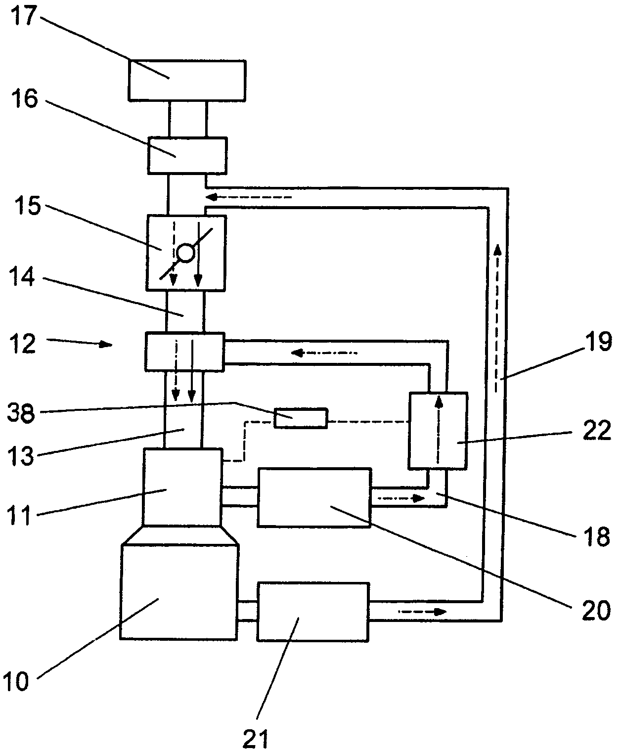
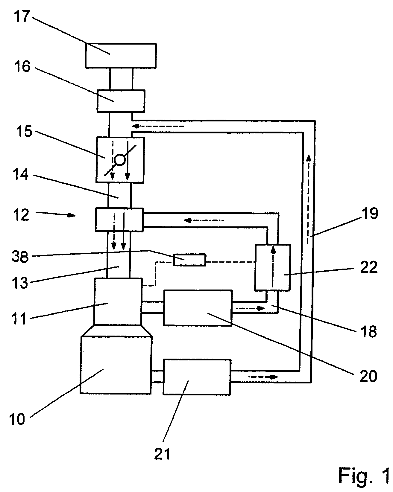
[0024]A crankcase 10 and a cylinder block 11 of a reciprocating-piston internal combustion engine are connected to one another in such a way that the pressure between them is substantially balanced. A first venting line 18, in which an oil separator 20 and, downstream of the latter, a control valve 22 are arranged, leads from the cylinder block 11. The first venting line 18, which is used to vent the crankcase 10 in a first, that is, part-load, operating range of the internal combustion engine opens into an intake line 14 of an intake system 12 downstream of a throttle valve 15. The intake line 14 is connected to an induction pipe 13 which is arranged on the cylinder block 11. The pressure in the induction pipe 13 substantially corresponds to the pressure in the intake line 14 downstream of a throttle valve 15.

[0025]A second venting line 19, in which another oil separator 21 is arranged, extends from the crankcase 10 to the intake line 14 upstream of the throttle valve 15. An air ma...


PUM


Abstract

In a method for venting a crankcase of an internal combustion engine, in which, in a first operating range under part-load, the crankcase is vented via a first venting line, which opens into an intake line of the internal combustion engine downstream of a throttle valve, and in a second operating range under full load engine operation, the crankcase is vented via a second venting line, which opens into the intake line upstream of the throttle valve, the first venting line includes a control valve and a central unit is provided which operates the control valve so as to control the flow of vent gases through the first venting line over a range including a complete flow interruption under engine overrun condition to prevent venting gases from reaching the engine exhaust system when the internal combustion engine is operating in an overrun mode.

Description

[0001]This is a Continuation-In-Part Application of International Application PCT / EP2004 / 007276 filed Jul. 3, 2004 and claiming the priority of German application 103 31 344.3 filed Jul. 11, 2003.BACKGROUND OF THE INVENTION[0002]The invention relates to a method and an apparatus for venting a crankcase of an internal combustion engine wherein, during partial load engine operation, the crankcase is in communication with the engine intake duct downstream of a throttle valve and, during full load engine operation the crankcase is in communication with the intake duct upstream of the throttle valve.[0003]When reciprocating-piston internal combustion engines are operating, pressure fluctuations occur in the crankcase as a result of the piston movements. The pressure of blow-by gases is superimposed on these pressure fluctuations. Blowby gases primarily comprise combustion gases which during combustion are formed at high pressure in the combustion chamber and pass via the piston ring seal...

Claims


Application Information

Patent Timeline
Patent Type & Authority Patents(United States)
IPC IPC(8): F01M13/00F01M13/02
CPCF01M13/025F01M13/022
Inventor BRUCHNER, KLAUSKAUFMANN, RALFKLEIN, RUDOLFMURWALD, MARIO
Owner DAIMLER AG
Why Eureka
Try Eureka