Operational ground support system

a ground support system and ground technology, applied in the direction of fuselages, weapons launch, transportation and packaging, etc., can solve the problems of time-consuming use of galley services, fueling, fueling, etc., to improve aircraft security, increase service efficiency, and improve the effect of interior spa

Inactive Publication Date: 2007-10-02
BLACK & DECKER INC +1
View PDF42 Cites 21 Cited by
  • Summary
  • Abstract
  • Description
  • Claims
  • Application Information

AI Technical Summary

Benefits of technology

[0015]The embodiments of the present invention provide several advantages. One such advantage is the provision of an integrated operational ground support system that allows for aircraft servicing through the nose or through automated service ports, located on the lower lobe regions forward of the wings on the port and starboard sides of the aircraft. The stated embodiment allows for passenger ingress / egress, cargo ingress / egress, primary system and secondary system servicing, and health and maintenance monitoring through the nose or simultaneously through the use of multiple level servicing bridges on port and starboard sides of the aircraft. In so providing, the stated embodiment provides increased servicing efficiency through simultaneous servicing thereof and provides improved aircraft security.
[0016]Servicing through the nose of an aircraft can eliminate the need for side passenger and cargo doors for ingress / egress of passengers and cargo. The elimination of side doors allows for interior space of the aircraft to be more efficiently utilized for increased passenger seating. Forward loading also enhances the cargo space within an aircraft. Forward loading or loading through the nose of an aircraft eliminates the need for a wing carry through center section that typically splits the cargo hold of an aircraft into forward and aft compartments. Front loading simplifies the structure and reduces the weight of an aircraft by utilizing a single set of front doors instead of fore and aft cargo doors. In addition, the front doors are located forward of aircraft areas that experience prime bending loads, which maintains proper door seating over time.
[0017]Furthermore, another advantage provided by an embodiment of the present invention is the provision of a terminal carry-on system that allows for the pre-loading of carry-on articles into carry-on transport modules. The carry-on system provides increased efficiency in passenger ingress and egress, aids in minimizing any apprehensions that passengers may have in becoming separated from their articles, and minimizes competition between passengers in first accessing or utilizing a overhead compartment storage area or the like. The terminal carry-on system significantly increases ingress and egress speed by facilitating the stowage and retrieval of personal articles within a terminal prior to and after embarkation. Passengers are able to ingress without carrying carry-ons to their respective seats without competition from co-passengers for overhead stowage. Upon arrival to a terminal, the passengers may egress from the aircraft and retrieve their personal effects within the terminal.
[0018]Yet another advantage provided by an embodiment of the present invention is the provision of operational ground support systems that utilize passenger transport modules. The passenger transport modules are used to shuttle passengers into and out of an aircraft. Again increasing passenger ingress / egress efficiency and providing an improved passenger overall flying experience. The passenger ingress / egress modules allow an aircraft to operate out of airports, which do not have the above-stated docking ports. The transport modules also allow an aircraft to operate at remote airport locations during instances of high gate demand.

Problems solved by technology

The potential for interference with passengers and servicing crewmembers exists in forward portions of the aircraft since the passengers deplane in the forward portion of the aircraft and passengers and servicing crewmembers use the same aisles of the aircraft.
The apron drive bridge is the most complex due to its rotating and telescoping capabilities, which allow for some freedom in parking location of an aircraft on an apron.
The use of galley servicing, cabin cleaning, fueling, air supply, electric supply, waste water disposal, potable water refurbishment, and cargo handling vehicles can be time consuming due to the steps involved in servicing the aircraft and the aircraft servicing location availability.
Aircraft servicing location availability is limited since most vehicle servicing of the aircraft can only be performed from the starboard side of the aircraft to prevent interference with the passenger bridge on the port side of the aircraft.
Mating of the servicing vehicles to the aircraft is also undesirable since an aircraft can potentially be damaged.
Current servicing of an aircraft is not efficient and current bridge designs are not physically applicable to newly introduced faster flying aircraft.
For example, a sonic cruiser is being studied by The Boeing Company that has a canard wing in an upper forward portion of the aircraft, which interferes with current passenger bridge designs.
System inefficiency of existing infrastructure and current aircraft fleet present restrictions encountered by the Sonic Cruiser.
Also, current systems and methods used for ground support of commercial aircraft are security limited.
It is difficult to provide and maintain adequate and appropriate security with regard to an aircraft, due to the number of different services accessing the aircraft at multiple locations along either side of the aircraft while at a terminal gate.
Additionally ground support services can also adversely affect passenger experience with flying, as a result of the somewhat chaotic fashion in which ground support services are currently provided.

Method used


Image

  • Operational ground support system
  • Operational ground support system
  • Operational ground support system

Examples


Embodiment Construction

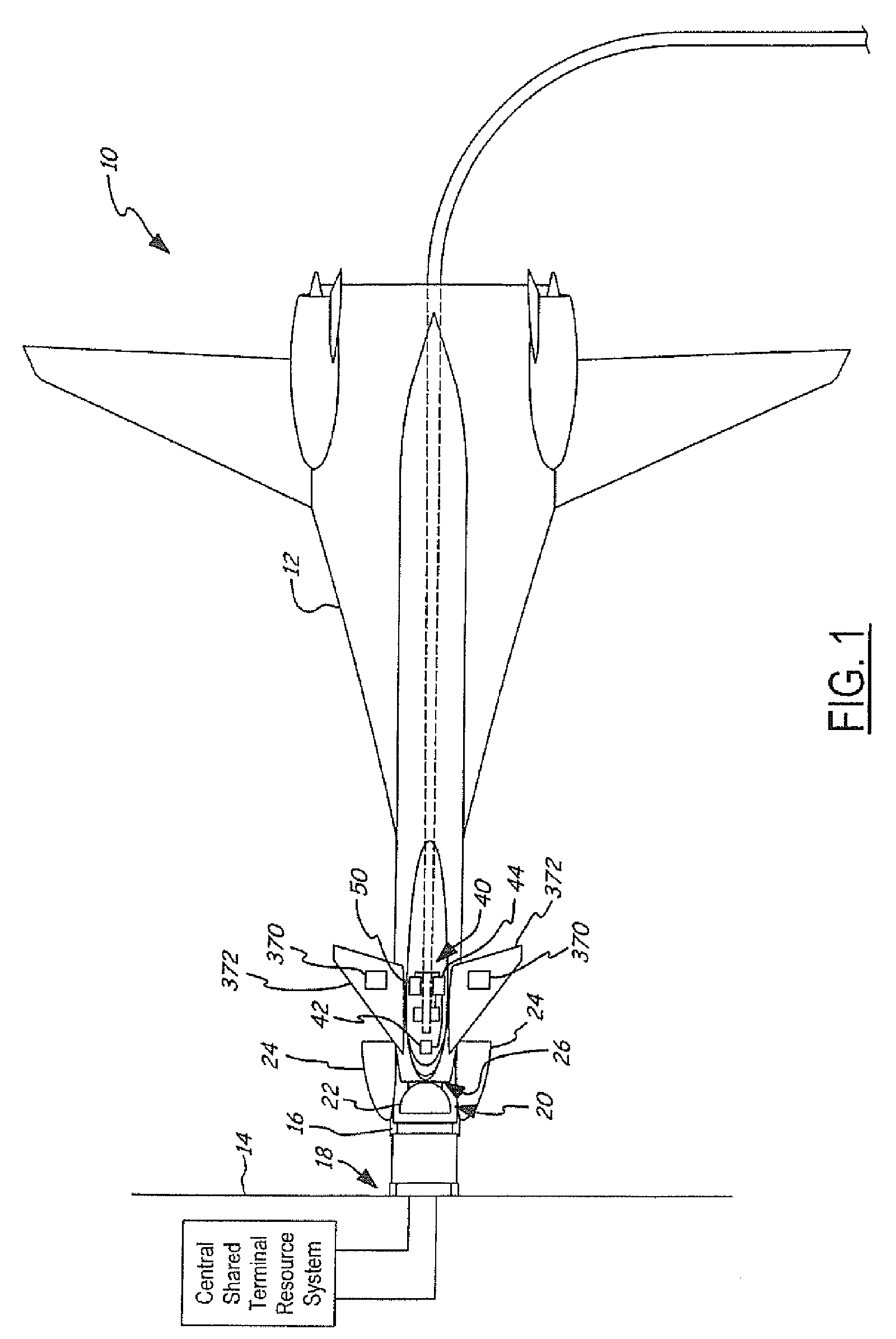
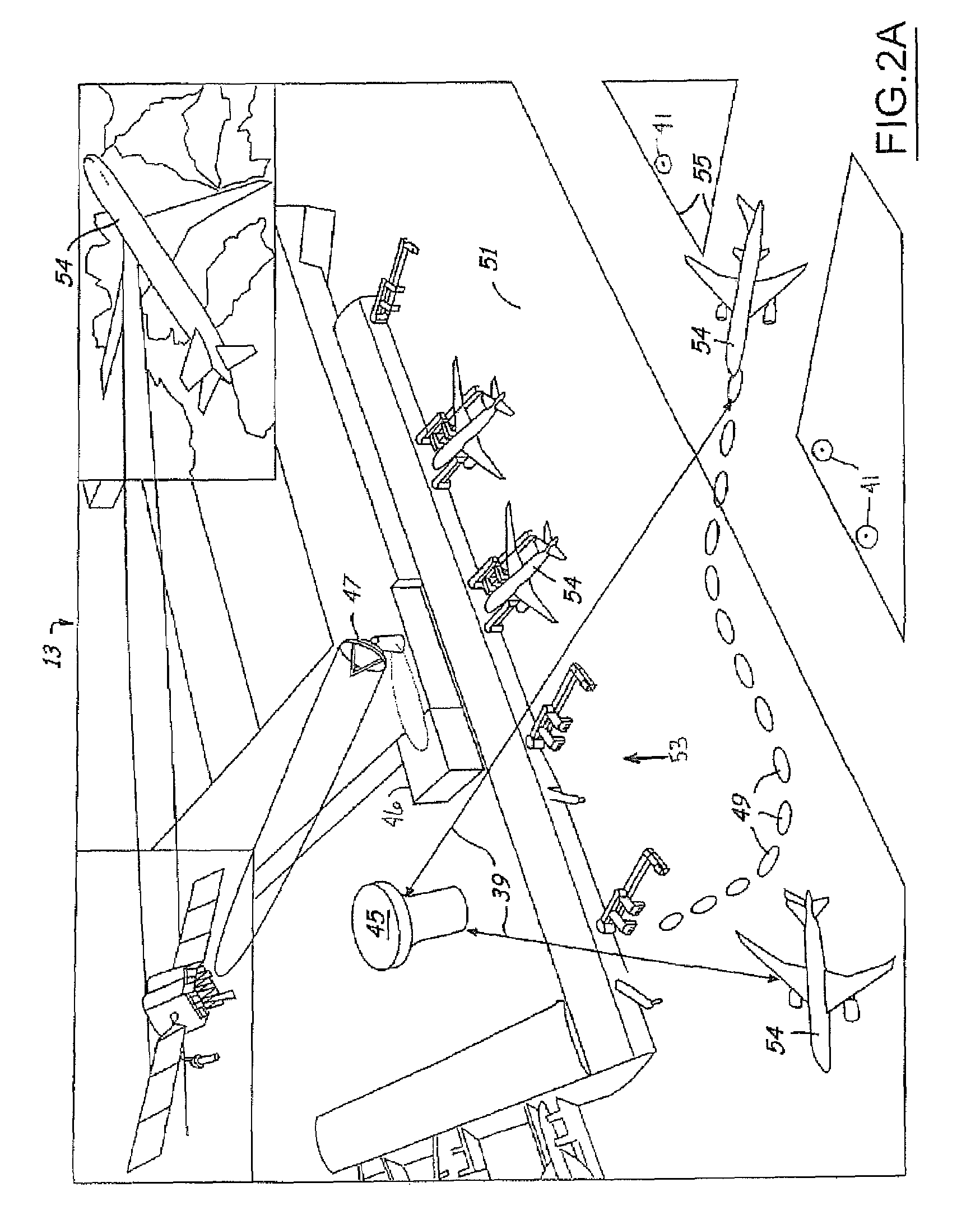
[0050]In each of the following Figures, the same reference numerals are used to refer to the same components. While the present invention is described with respect to systems and methods of servicing an aircraft, the present invention may be adapted for various applications and systems including: aeronautical systems, land-based vehicle systems, or other applications or systems known in the art that require servicing of a vehicle.

[0051]In the following description, various operating parameters and components are described for one constructed embodiment. These specific parameters and components are included as examples and are not meant to be limiting.

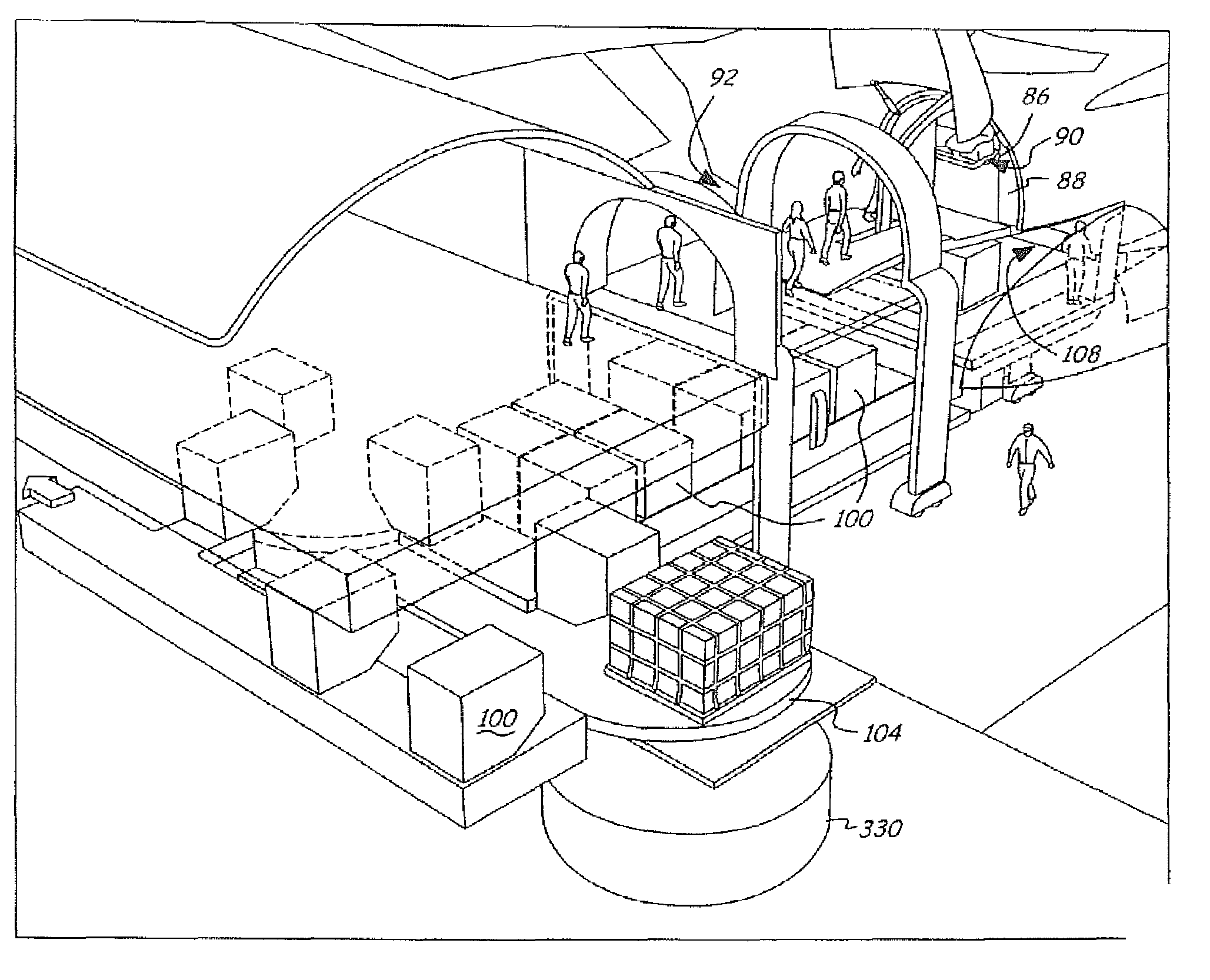
[0052]Also, in the following description the terms “service”, “services”, and “servicing” may include and / or refer to any aircraft services, such as passenger ingress / egress services, cargo ingress / egress services, aircraft primary services, aircraft secondary services, galley services, cabin cleaning services, lavatory services, or oth...


PUM


Abstract

An integrated operational ground mobility and support system (10) that includes an aircraft (12) having one or more service openings on a side of the aircraft (12). The integrated support system (10) may have an airport interface terminal docking port (14) that has a ground support service sub-system. The docking port (14) mates with the aircraft (12) at the service openings and has multiple service levels. The ground support service sub-system provides services to the aircraft (12) through the service openings and on the service levels. The integrated support system (10) may have in addition to or in replacement of the interface terminal docking port an aircraft loader / unloader. The loader / unloader has ground support service sub-systems and mates with the aircraft (12) at one or more of the service openings. The service sub-systems of the loader / unloader include a passenger ingress / egress system (62) and provide services to the aircraft (12).

Description

RELATED APPLICATION[0001]The present application is a continuation-in-part (CIP) application of U.S. patent application Ser. No. 10 / 847,739, filed on May 17, 2004, entitled “Operational Ground Support System,” which is incorporated by reference herein.TECHNICAL FIELD[0002]The present invention relates generally to aeronautical vehicle ground support systems and automated, controlled ground mobility. More particularly, the present invention relates to integrated systems and methods of providing ground support services and controlled mobility between touch down and takeoff of an aircraft.BACKGROUND OF THE INVENTION[0003]It is desirable within the airline industry to provide efficient aircraft servicing and ground mobility. Time involved in taxiing to and from gates and in performing various servicing tasks, is directly related to the amount of time an aircraft is able to spend in flight. The more an aircraft is in flight the higher the potential profits associated with that aircraft.[...

Claims


Application Information

Patent Timeline
Patent Type & Authority Patents(United States)
IPC IPC(8): B64C9/00B64C27/22B64F1/305B64F1/31B64F1/36
CPCB64C25/405B64F1/305B64F1/36B64F1/31Y02T50/823Y02T50/82Y02T50/80
Inventor MCCOSKEY, WILLIAM R.JOHNSON, RICHARD N.RENTON, W. JAMES
Owner BLACK & DECKER INC
Why Eureka
Try Eureka