
Irrigated ablation device assembly

a technology of irrigated ablation and assembly, which is applied in the field of surgical devices, can solve the problems of adverse medical effects, inability to achieve substantial efficacy, and high invasive methodology, and achieve the effect of reducing the risk of infection, and reducing the effect of invasiveness

Inactive Publication Date: 2007-10-02
ATRIONIX
View PDF59 Cites 233 Cited by
  • Summary
  • Abstract
  • Description
  • Claims
  • Application Information

AI Technical Summary

Benefits of technology

"The present invention relates to a medical device assembly for ablating a region of tissue in a patient's body space wall. The assembly includes an ablation member with an ablation element and a porous membrane. The porous membrane is positioned over the ablation element and allows fluid to pass through it. The assembly also includes a fluid delivery passageway and a porous sheath member that can be positioned within the body space to deliver fluid to the ablation member. The invention also includes a method of constructing an elongated medical article by fusing two tubular members together. The technical effects of the invention include improved fluid irrigation and the ability to position the ablation member in multiple layers."

Problems solved by technology

However, more recent reports predict that the surgical “maze” procedure may be substantially efficacious when performed only in the left atrium, such as is disclosed in Sueda et al., “Simple Left Atrial Procedure for Chronic Atrial Fibrillation Associated With Mitral Valve Disease” (1996).
While surgical intervention such as the “maze” procedure has been moderately successful in treating atrial arrhythmia, this highly invasive methodology is believed to be prohibitive in many cases.
A threshold temperature that has been disclosed for ablating tissue according to a thermal conduction mode of ablation is generally above 45 degrees C. usually from 45 to 70 degrees C., typically 50 to 65 degrees C., and preferably from about 53 to 60 degrees C. It has also been observed that high temperatures, such as temperatures above 70 degrees C., may produce charring at the tissue-ablation element interface, It has been further observed that such charring may cause adverse medical results such as thrombosis on the tissue wall in the case of tissue ablation of the cardiac chambers including the atrium.
Current flowing between the electrode and the patch is at its highest density at the tissue location adjacent to the treatment electrode, and therefore causes ablation of the tissue.
Focal tissue ablation, however, is not generally believed to be appropriate for many cases of atrial fibrillation of the “multi-wavelet” type which involve multiple reentrant loops which are believed to arise from various arrhythmogenic sources.
Moreover, it has been observed that this process may fail to produce continuous, transmural lesions, thus leaving the opportunity for the reentrant circuits to reappear in the gaps remaining between point or drag ablations.

Method used


Image

  • Irrigated ablation device assembly
  • Irrigated ablation device assembly
  • Irrigated ablation device assembly

Examples


Embodiment Construction

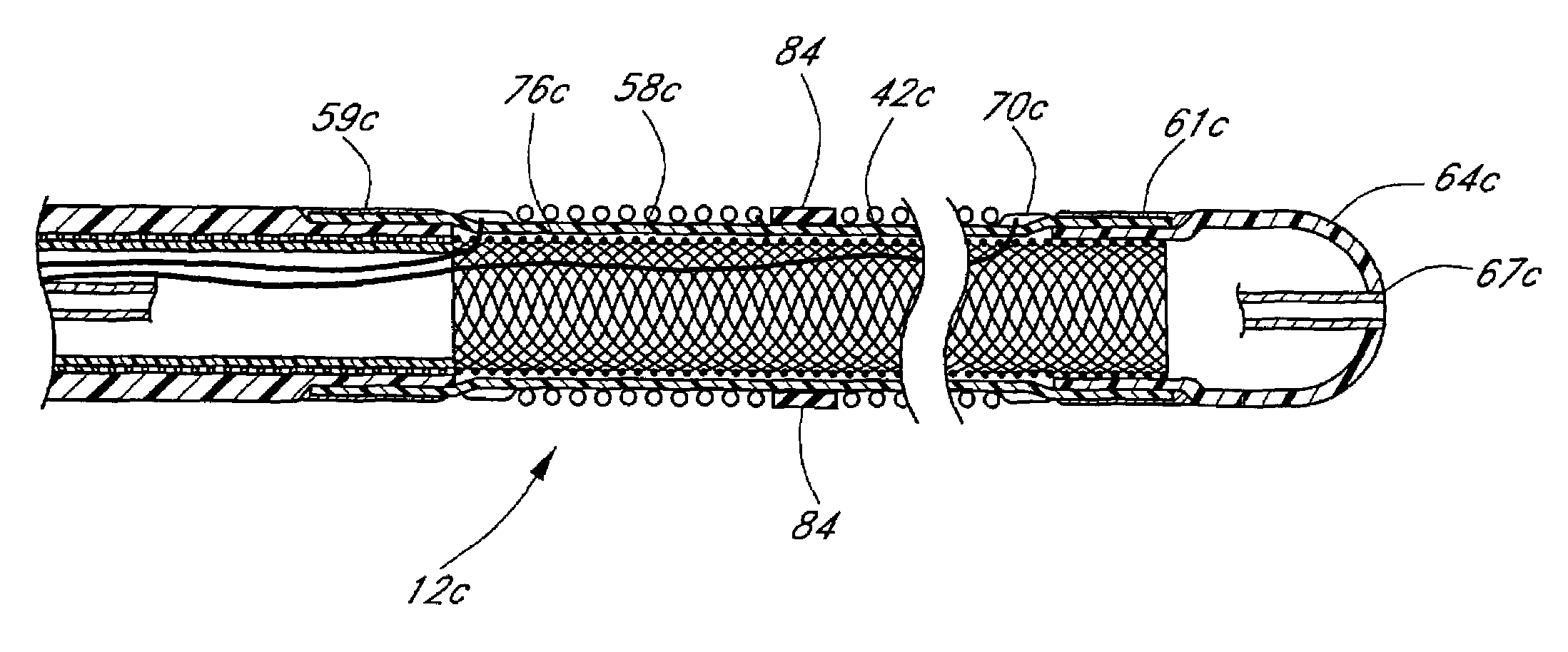
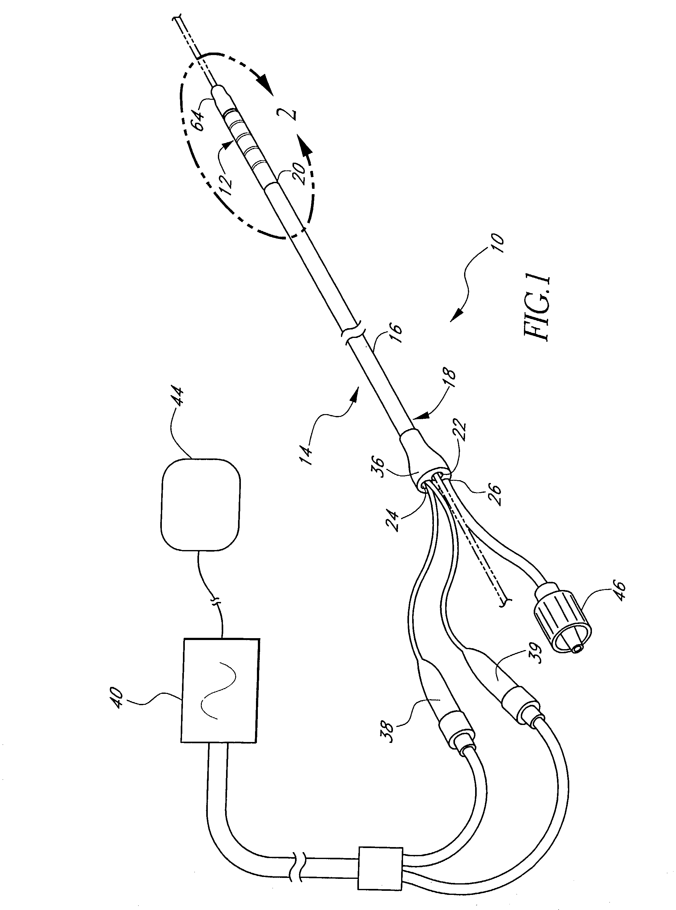
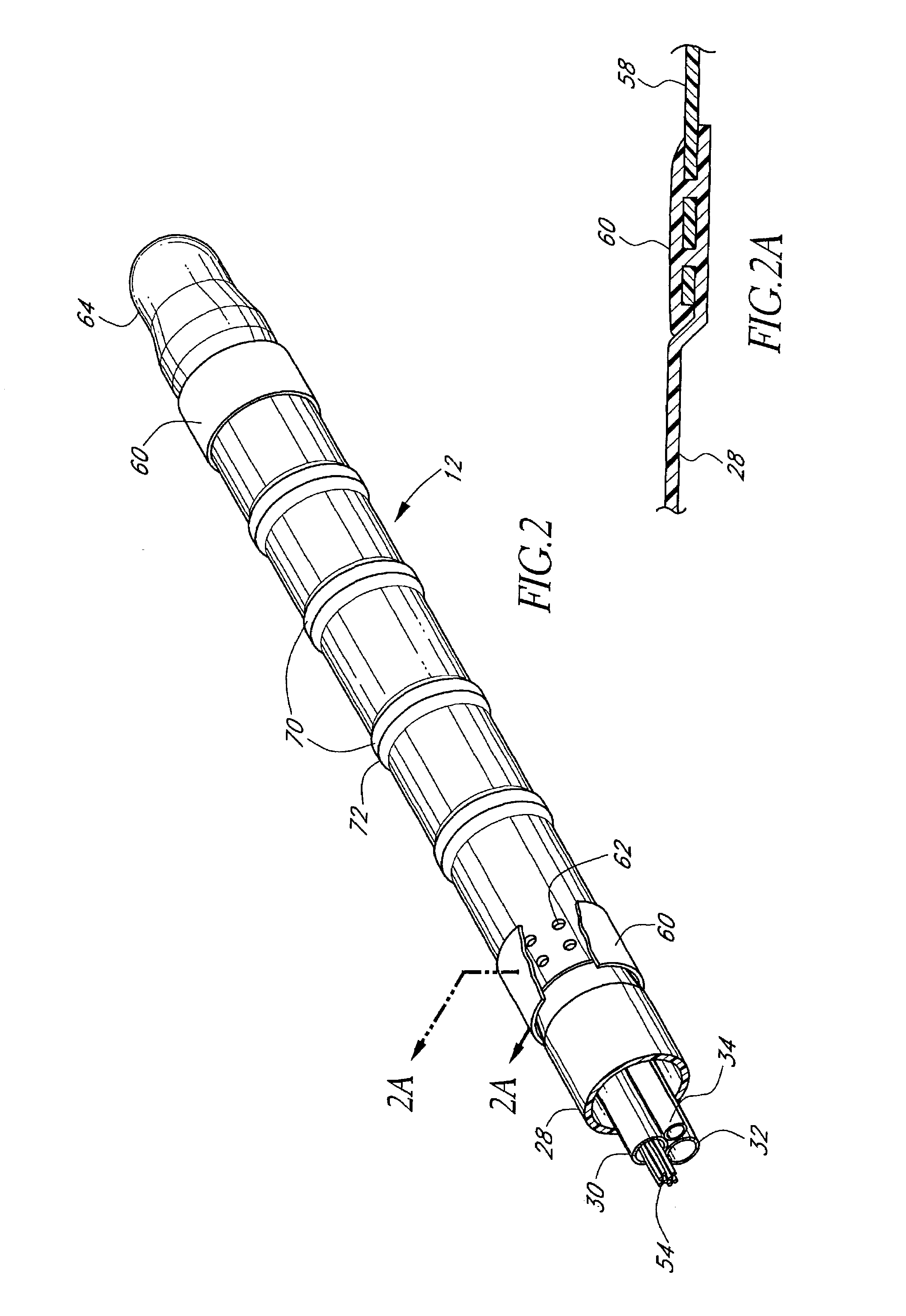
[0071]FIG. 1 illustrates a tissue ablation device assembly 10 with an irrigated ablation member 12 configured in accordance with a preferred variation of the present invention. The present ablation member 12 has particular utility in connection with forming a linear lesion within myocardial tissue of a left atrium of a mammal's heart. The application of the present ablation member, however, is merely exemplary, and it is understood that those skilled in the art can readily adapt the present irrigated ablation member 12 for applications in other body spaces, as well as to ablate other shape lesions.

[0072]The ablation member 12 is attached to a delivery member 14 in order to access and position the ablation member 12 at the site of the target tissue. In the illustrated mode, the delivery member takes the form of an exemplary over-the-wire catheter. The delivery member 14 comprises an elongated body 16 with proximal 18 and distal end portions 20. As used herein, the terms “distal” and ...


PUM


Abstract

A tissue ablation device assembly ablates a region of tissue in a body of a patient. The tissue ablation device assembly comprises an elongated body having a proximal end portion and a distal end portion. A tubular porous membrane having a porous wall with an inner surface that defines an inner space is located along the distal end portion of the elongated body. An ablation element is disposed over the porous membrane, with the ablation element having a fixed position with respect to the porous membrane. A fluid passageway extending through the elongated body and communicates with the inner space. The fluid passageway is adapted to be fluidly coupled to a pressurizeable fluid source for delivering a volume of pressurized fluid from the fluid source to the inner space. The porous membrane allows at least a substantial portion of the volume of pressurized fluid to pass through the porous wall for enhancing ablative coupling between the electrode and the region of tissue.

Description

RELATED APPLICATIONS[0001]This application is a continuation of U.S. patent application Ser. No. 09 / 073,907 filed on May 6, 1998, now U.S. Pat. No. 6,522,930, to which this application priority under 35 U.S.C. § 120.BACKGROUND OF THE INVENTION[0002]1. Field of the Invention[0003]The present invention is a surgical device. More specifically, the present invention relates to a tissue ablation device assembly with an irrigated ablation member which is adapted to produce a lesion within tissue. The present invention also relates to the construction of the ablation member.[0004]2. Description of Related Art[0005]Cardiac arrhythmias, and atrial fibrillation in particular, remain a persistent medical condition in modern society. Persistence of atrial fibrillation has been observed to cause or at least contribute to various medical conditions including congestive heart failure, stroke, other thromboembolic events, and myocardial ischemia.[0006]Several surgical approaches have been developed...

Claims


Application Information

Patent Timeline
Patent Type & Authority Patents(United States)
IPC IPC(8): A61B18/14A61B18/04A61B18/00
CPCA61B18/1492A61B2017/22038A61B2018/00011A61B2018/00029A61B2018/00065A61B2218/002A61B2018/00214A61B2018/00797A61B2018/00821A61B2018/1437A61B2018/0016
Inventor SCHAER, ALAN K.VALENCIA, AURELIO
Owner ATRIONIX
Learn More