
Multifilar flexible rotary shaft and medical instruments incorporating the same

a flexible rotary shaft and multi-filament technology, applied in the field of flexible rotary shafts, can solve the problems of increased hysteresis, difficult to handle as a sub-assembly, and nevertheless have their own disadvantages, so as to reduce hysteresis

Inactive Publication Date: 2007-10-02
BOSTON SCI SCIMED INC
View PDF147 Cites 20 Cited by
  • Summary
  • Abstract
  • Description
  • Claims
  • Application Information

AI Technical Summary

Benefits of technology

[0015]It is therefore an object of the invention to provide a flexible rotary shaft which has reduced hysteresis.
[0016]It is also an object of the invention to provide a flexible rotary shaft which has increased torque transmission.
[0018]It is still another object of the invention to provide a flexible rotary shaft which has accurate torque transmission when reversing from one rotational direction to the opposite rotational direction.

Problems solved by technology

While these constructions overcome the deficiency of monofilar flexible rotary shafts, they nevertheless have their own disadvantages.
The most notable disadvantage of multifilar flexible rotary shafts is increased hysteresis which results from internal friction among the filaments.
Internal friction and hysteresis in multifilar flexible rotary shafts results from the manner in which they are constructed.
If such cables were not made in this way, they would be very difficult to handle as a subassembly because they would spring apart when the ends were cut.
Because of this, there are considerable compressive contact forces among the wires, resulting in friction between the wires when the shaft is rotated while traversing a curved path.
This internal wire-to-wire friction results in energy absorption in the flexible shaft, so that energy delivered to the output end is less than the energy applied to the input end.
This reaction to torque thus results in contact forces between the layers of wire, and these contact forces result in friction.
As a result, there is noticeable lost rotary motion at the output end of the flexible shaft when the input torque is alternated from one direction to the other, as in the case of a shaft used to steer a medical device or to transmit a rotary position signal.
This hysteresis is made worse when the flexible shaft traverses a curved path, because additional stresses between the layers (resulting in increased internal friction) are introduced by the bending of the shaft through a curved path.
While these shafts may work well enough in the unidirectional transmission of power, they are ineffective in precisely transmitting rotary control (in two rotational directions) because of the hysteresis or “lost motion” caused by their internal friction.

Method used


Image

  • Multifilar flexible rotary shaft and medical instruments incorporating the same
  • Multifilar flexible rotary shaft and medical instruments incorporating the same
  • Multifilar flexible rotary shaft and medical instruments incorporating the same

Examples


Embodiment Construction

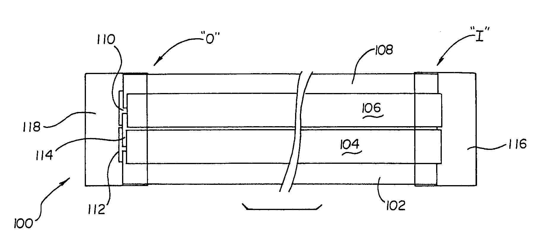
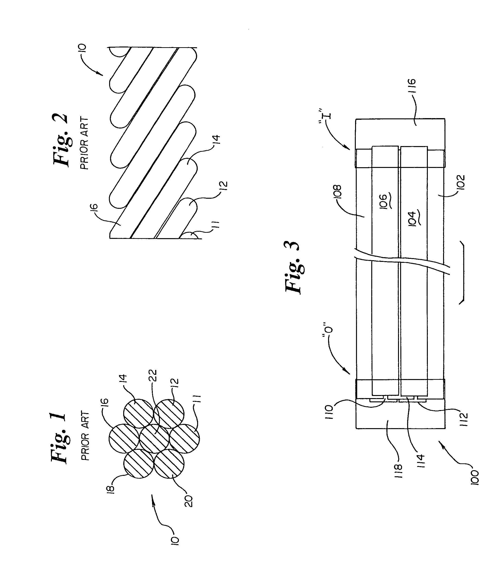
[0032]Referring now to FIG. 3, a multifilar flexible rotary shaft 100 according to the present invention includes a plurality of individual filaments, e.g. 102, 104, 106, 108, 110, 112, 114. Each filament has an input end, designated generally as “I” in FIG. 3 and an output end, designated generally as “O” in FIG. 3. All of the input ends are coupled to each other, for example by a coupling 116. All of the output ends are coupled to each other, for example by a coupling 118. The filaments are not tightly wound around each other or around a central core. However, they may be wound together loosely merely to facilitate handling of the shaft. Preferably all of the filaments are identical and, for a plurality of N wires, each wire has 1 / N the yield stress required to transmit the maximum torque required for the shaft.

Discussion of Physical Principals of the Invention

[0033]If a torque is applied to a free mechanical body, that body will begin to take on an accelerating angular velocity. ...


PUM


Abstract

A multifilar flexible rotary shaft includes a plurality of individual filaments which are not wound around each other or around a central core, a loose ensemble of filaments. The input ends of each filament are coupled to each other and the output ends of each filament are coupled to each other. Preferably all of the filaments are identical. A loose ensemble of N filaments can transmit N times the torque of a single filament, and will have N times the torsional stiffness of a single filament, while retaining the minimum radius of operation of a single filament. Since a loose ensemble of filaments does not have any appreciable contact forces among the filaments (because they are not forcibly twisted together), there is no appreciable internal friction or hysteresis. In order to appreciably eliminate all the hysteresis in such an ensemble of filaments, the filaments should be no more than loosely twisted together, if at all. The only reason for loosely twisting the wires together is to allow the ensemble to be easily handled and to insure that the individual wire filaments follow the same general curved path from one end to the other. Several practical applications of the invention are also disclosed.

Description

CROSS-REFERENCE TO CO-PENDING APPLICATIONS[0001]This application is a continuation of U.S. application Ser. No. 10 / 155,584, filed May 24, 2002, now U.S. Pat. No. 6,761,717; which is a continuation of U.S. application Ser. No. 09 / 418,769, filed Oct. 15, 1999, now U.S. Pat. No. 6,409,727.[0002]This application is related to co-owned application Ser. No. 09 / 369,724 filed Aug. 6, 1999, now U.S. Pat. No. 6,235,026 and entitled “Polypectomy Snare Instrument” the complete disclosure of which is hereby incorporated by reference herein.BACKGROUND OF THE INVENTION[0003]1. Field of the Invention[0004]The invention relates to flexible rotary shafts. More particularly, the invention relates to a multifilar flexible rotary shaft having reduced hysteresis, increased torque transmission, and low internal friction. The shaft of the invention is particularly useful as a component of minimally invasive surgical instruments which must traverse a tortuous path.[0005]2. State of the Art[0006]Flexible rot...

Claims


Application Information

Patent Timeline
Patent Type & Authority Patents(United States)
IPC IPC(8): A61B18/18A61B17/221D07B1/00A61B17/28A61B17/32A61B18/04A61C1/18A61M25/01F16C1/02F16C1/08
CPCA61B17/320016A61B17/32056F16C1/08F16C1/02A61B17/32002A61B2017/2905A61B2017/2929A61B2017/2902F16C2316/10
Inventor BALES, THOMAS O.KORTENBACH, JUERGEN A.
Owner BOSTON SCI SCIMED INC
Learn More