Piezoelectric thin-film resonator and process for producing same

a thin-film resonator and piezoelectric technology, applied in the field can solve problems such as degrading the q-value of piezoelectric thin-film resonators, and achieve the effect of low cos

Inactive Publication Date: 2007-10-02
MURATA MFG CO LTD
View PDF8 Cites 21 Cited by
  • Summary
  • Abstract
  • Description
  • Claims
  • Application Information

AI Technical Summary

Benefits of technology

[0008]In view of this, it is an object of the present invention to provide a piezoelectric thin-film resonator capable of reducing loss of energy in an acoustic reflecting layer to improve Q of the piezoelectric thin-film resonator, and to provide a process for producing the piezoelectric thin-film resonator.
[0029]In this case, it is possible to produce the piezoelectric thin-film resonator at low cost compared with a method for patterning the acoustic reflecting layer by dry etching.

Problems solved by technology

Therefore, loss of energy of the acoustic wave occurs in the acoustic reflecting layer, thus disadvantageously degrading the Q-value of the piezoelectric thin-film resonator.

Method used


Image

  • Piezoelectric thin-film resonator and process for producing same
  • Piezoelectric thin-film resonator and process for producing same
  • Piezoelectric thin-film resonator and process for producing same

Examples


first embodiment

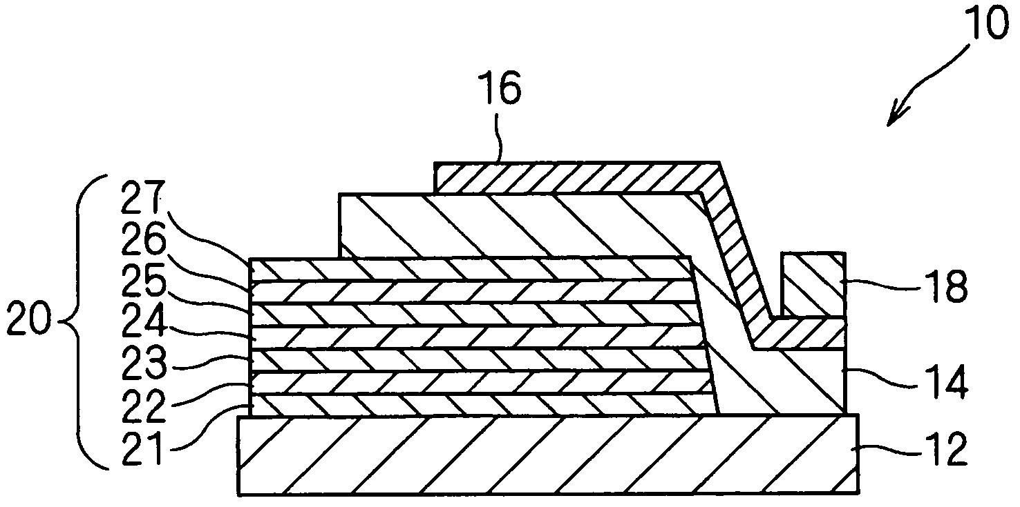
[0037]A piezoelectric thin-film resonator 10 will be described with reference to FIGS. 1, 3, and 5.

[0038]FIG. 1 is a fragmentary cross-sectional view illustrating the piezoelectric thin-film resonator 10 according to a first embodiment of the present invention. The piezoelectric thin-film resonator 10 includes a lower electrode 20, a piezoelectric thin film 14, an upper electrode 16, and an upper thick electrode 18 that are formed on a substrate 12 in that order.

[0039]A LiTaO3 or LiNbO3 single-crystal substrate is used as the substrate 12.

[0040]The lower electrode 20 includes an acoustic reflecting layer on the substrate 12. Different conducting materials between which a mismatch in the lattice constants is small are alternately deposited on the substrate 12 by epitaxial growth to form alternately laminated sublayers 21 to 27, the sublayers 21 to 27 constituting the lower electrode 20. The sublayers 21 to 27 are formed by a film-forming method, such as evaporation or sputtering, in...

second embodiment

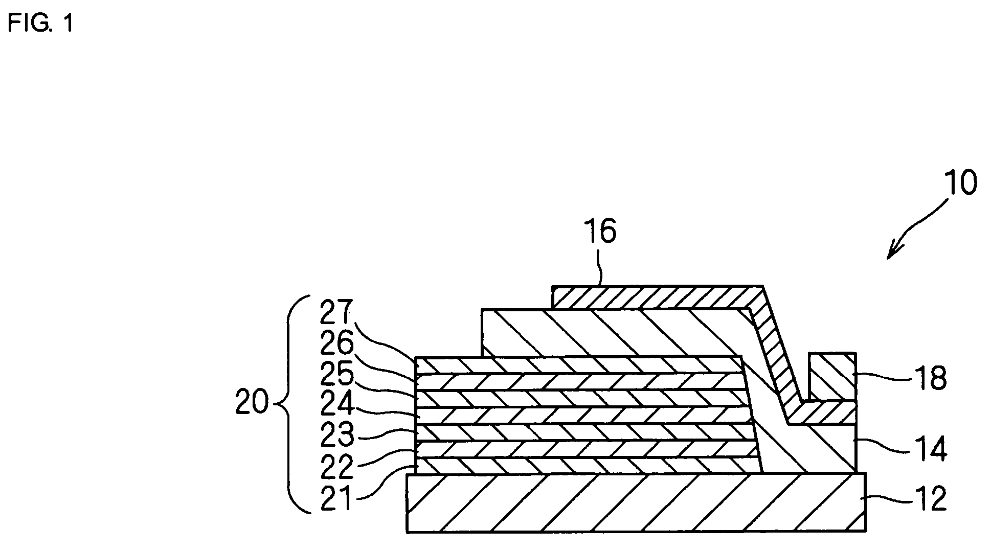
[0075]A piezoelectric thin-film resonator 30 will be described below with reference to FIG. 2.

[0076]FIG. 2 is a fragmentary cross-sectional view illustrating the structure of the piezoelectric thin-film resonator 30. The piezoelectric thin-film resonator 30 has the same structure as that of the piezoelectric thin-film resonator 10 according to the first embodiment except that an upper electrode 50 includes an acoustic reflecting layer.

[0077]The piezoelectric thin-film resonator 30 according to the second embodiment includes a lower electrode 40, a piezoelectric thin film 34, and an upper electrode 50, provided in that order, on a substrate 32.

[0078]The substrate 32 is composed of a LiTaO3 or LiNbO3 single crystal. The lower electrode 40 includes acoustic reflecting layer. The lower electrode 40 includes a plurality of sublayers 41 to 47 and formed by a film-forming method, such as evaporation or sputtering in a manner such that a high acoustic impedance sublayer and a low acoustic ...


PUM

PropertyMeasurementUnit
thicknessaaaaaaaaaa
thicknessaaaaaaaaaa
thicknessaaaaaaaaaa

Abstract

A piezoelectric thin-film resonator includes a first excitation electrode and a second excitation electrode, the first excitation electrode being disposed opposite the second excitation electrode; a piezoelectric thin film disposed between the first excitation electrode and the second excitation electrode; and a substrate supporting the first excitation electrode, the substrate being composed of a LiTaO3 single crystal or a LiNbO3 single crystal, the first excitation electrode including an acoustic reflecting layer, the acoustic reflecting layer containing (a) at least one epitaxially grown first sublayer being composed of a conducting material and having a relatively high acoustic impedance; and (b) at least one epitaxially grown second sublayer being composed of another conducting material and having a relatively low acoustic impedance.

Description

BACKGROUND OF THE INVENTION[0001]1. Field of the Invention[0002]The present invention relates to a piezoelectric thin-film resonator and a process for producing the same. In particular, the present invention relates to a piezoelectric thin-film resonator including an acoustic reflecting layer acoustically separating a thin-film portion containing a piezoelectric thin film sandwiched between a pair of electrodes from a substrate, and a process for producing the same.[0003]2. Description of the Related Art[0004]An example of a piezoelectric thin-film resonator using a bulk acoustic wave (BAW) in a piezoelectric thin film is a piezoelectric thin-film resonator using an acoustic reflecting layer acoustically separating a thin-film portion containing a piezoelectric thin film sandwiched between a pair of electrodes from a substrate.[0005]With respect to such a piezoelectric thin-film resonator, for example, Japanese Unexamined Patent Application Publication No. 2002-278558 proposes a str...

Claims


Application Information

Patent Timeline
Patent Type & Authority Patents(United States)
IPC IPC(8): H01L41/047H01L41/083H03H9/24H01L41/09H01L41/18H01L41/187H01L41/22H01L41/29H03H3/02H03H9/17
CPCH03H3/04H03H9/02149H03H9/172H03H9/131Y10T29/42H03H9/175
Inventor UMEDA, KEIICHINAKAGAWARA, OSAMU
Owner MURATA MFG CO LTD
Why Eureka
Try Eureka