Steam turbine plant

a steam turbine plant and steam turbine technology, applied in the direction of machines/engines, mechanical equipment, lighting and heating apparatus, etc., can solve the problems of low thermal efficiency, inability to use the kind of modified conventional steam turbine plant, and inability to produce hydrogen. to achieve the effect of improving the efficiency of the plan

Inactive Publication Date: 2007-10-09
KK TOSHIBA
View PDF12 Cites 33 Cited by
  • Summary
  • Abstract
  • Description
  • Claims
  • Application Information

AI Technical Summary

Benefits of technology

[0018]Accordingly, an advantage of an aspect of the present invention is to provide a steam turbine plant that partially utilizes a hydrocarbon fuel such as an LNG as a fuel to improve the efficiency of the plant.
[0019]To achieve the above advantage, one aspect of the present invention is to provide a steam turbine plant that comprises a boiler that generates steam, a steam turbine driven by the steam generated in the boiler, a feedwater system that recovers the steam exhausted from the steam turbine and supplies the steam to the boiler as feedwater, and a superheating combustor provided between the boiler and the steam turbine, wherein fuel originated from a hydrocarbon fuel and an oxidizer are mixed with the steam generated in the boiler and combusted in the superheating combustor to increase the temperature of the steam.

Problems solved by technology

However, because it utilizes a gas turbine, the fuel has to be clean to avoid trouble with turbine components which might be caused by impurities contained in the fuel.
It is said that coal is more abundant on earth than LNG However, coal usually contains many impurities and conventionally, is not suitable for a fuel in the gas turbine or the combined cycle plant.
Some modifications for these conventional steam turbine plants, such as hydrogen utilization, have been attempted because of relatively low thermal efficiency of the conventional coal thermal power plant.
So far, the cost to produce hydrogen is too high even in view of the improvement in thermal efficiency.
Therefore, this kind of modified conventional steam turbine plant has not been in practical use.

Method used


Image

  • Steam turbine plant
  • Steam turbine plant
  • Steam turbine plant

Examples


Embodiment Construction

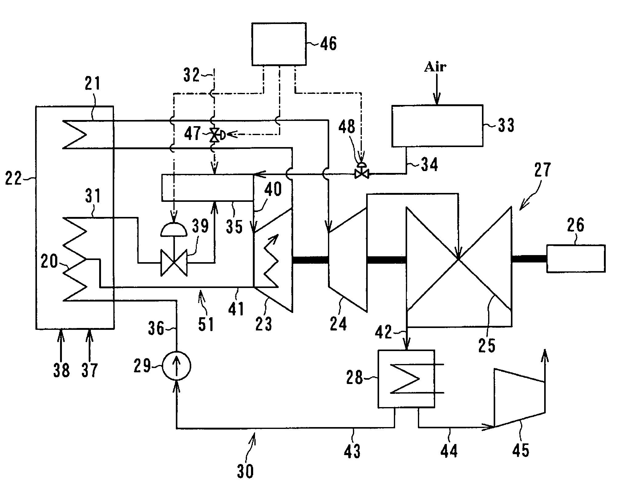
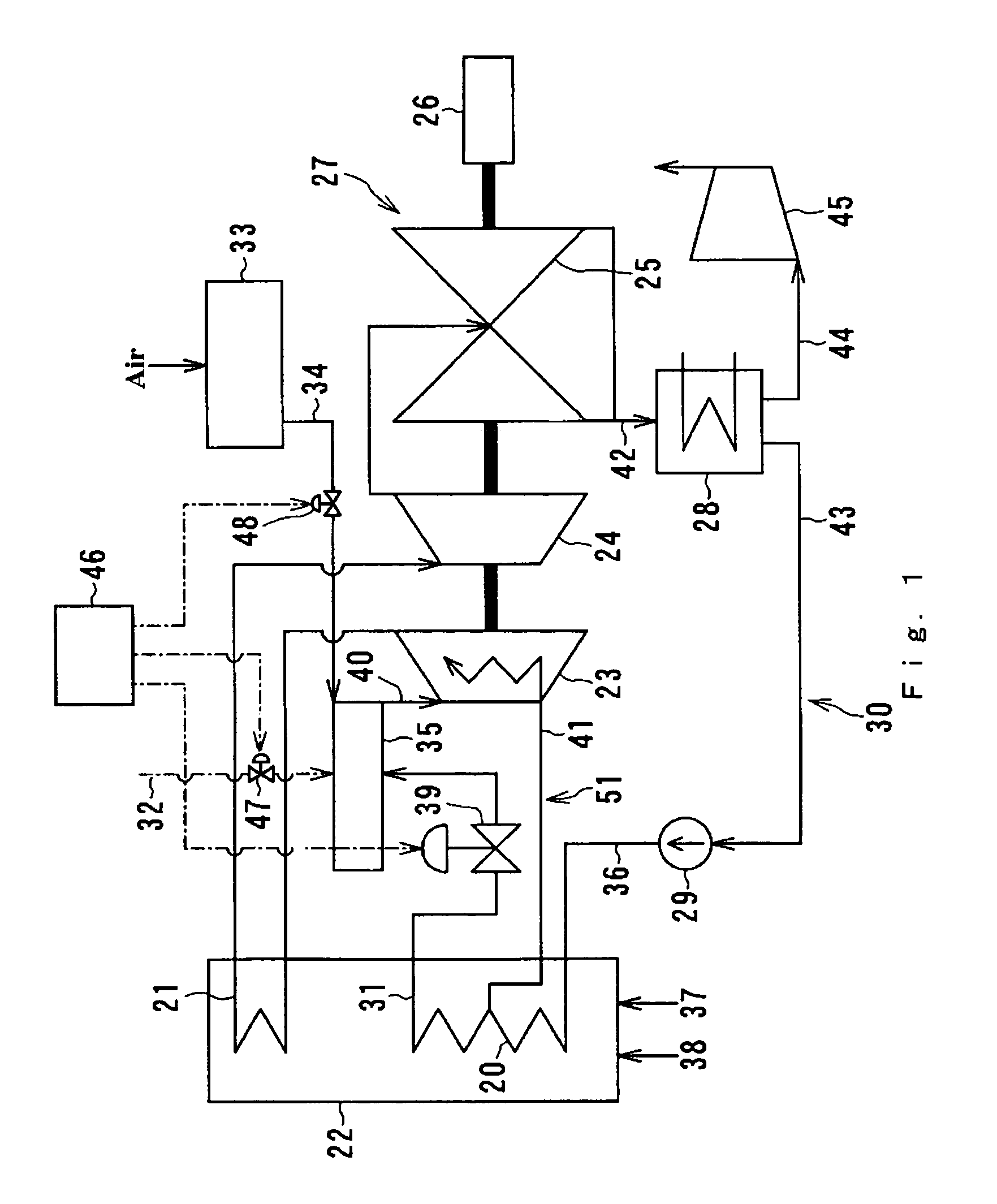
[0027]FIG. 1 is a schematic diagram of a first embodiment of a steam turbine plant in accordance with the present invention.

[0028]The steam turbine plant in accordance with the first embodiment comprises a boiler 22, a steam turbine 27, a feedwater system 30, and a superheating combustor 35. Boiler 22 includes a steam generator 20 and a reheater 21. Steam turbine 27 includes a high pressure turbine 23, an intermediate pressure turbine 24, and a low pressure turbine 25. The rotation shaft of high pressure turbine 23, intermediate pressure turbine 24, low pressure turbine 25 are coupled together as one and connected to a generator 26.

[0029]Feedwater system 30 includes a condenser 28, a condensate line 43, a feedwater pump 29, and a feedwater line 36. The feedwater system recovers steam from the low pressure turbine 25. The steam from the low pressure turbine condenses into water as condensate in the condenser 28 and led to the feedwater line 36 through condensate line 43 and feedwater...


PUM


Abstract

A steam turbine plant partially utilizes a hydrocarbon fuel such as an LNG as a fuel to improve the efficiency of the plant. A steam turbine plant includes a boiler, a steam turbine, a feedwater system, and a superheating combustor. The boiler generates steam, and the steam turbine is driven by the steam generated in the boiler. The feedwater system recovers the steam exhausted from the steam turbine and supplies the steam to the boiler as a feedwater. The superheating combustor is provided between the boiler and the steam turbine, wherein fuel originated from hydrocarbon fuel and oxidizer are mixed with the steam generated in the boiler and combusted in the superheating combustor to increase the temperature of the steam.

Description

CROSS REFERENCE TO RELATED APPLICATION[0001]This application is based upon and claims the benefit of priority from prior Japanese Patent Application No. 2004-47939 filed on Feb. 24, 2004, the entire contents of which are incorporated herein by reference.FIELD OF THE INVENTION[0002]This invention relates to a steam turbine plant, and in particular a steam turbine plant that can improve the efficiency of the plant.DESCRIPTION OF THE BACKGROUND[0003]With regard to a thermal power plant, one factor to improve thermal efficiency of the plant is a choice of a fuel used in the plant.[0004]A combined cycle plant is a thermal power plant that combines a gas turbine and a steam turbine. Conventional combined cycle plants use liquefied natural gas (referred to as LNG), which contains very few impurities, as a fuel and achieves over 50% net generating efficiency.[0005]The combined cycle plant can achieve high thermal efficiency, as mentioned above, because of its nature, which is a combination ...

Claims


Application Information

Patent Timeline
Patent Type & Authority Patents(United States)
IPC IPC(8): F02C3/30F01K21/04F01K3/24F01K25/00F22G1/12
CPCF01K3/24F22G1/12Y02E20/16Y02E20/34
Inventor YAMADA, MASAHIKOYAMASHITA, KATSUYAGOTO, KOICHINAKAGAKI, TAKAO
Owner KK TOSHIBA
Why Eureka
Try Eureka