Power supply device with dead-time control and printing apparatus having the same

a technology of power supply device and printing apparatus, which is applied in the direction of power conversion system, dc-dc conversion, instruments, etc., can solve the problems of overcurrent protection circuit operation error, overcurrent surge, and failure of main switching element qb>101/b>, so as to reduce the input rush current and reduce the time

Inactive Publication Date: 2007-10-09
CANON KK
View PDF10 Cites 23 Cited by
  • Summary
  • Abstract
  • Description
  • Claims
  • Application Information

AI Technical Summary

Benefits of technology

[0023]It is an object of the present invention to reduce an input rush current generated when changing an output voltage during operation, and to reduce the time required to cause the output voltage to reach the setting voltage in a power supply device including a DC / DC converter which can widely change the output voltage on the basis of a voltage setting signal from an external device.
[0027]Hence, since the control signal appropriately changes the dead-time control voltage, the output voltage from the DC / DC converter can efficiently change within a short period of time.

Problems solved by technology

The excessive current flows, and the main switching element Q101 may fail.
Furthermore, an operation error may occur in the overcurrent protective circuit for an input-side AC adapter and battery.
Alternatively, when a signal which reduces the setting voltage is output from the control unit 3 in an output state with no load, the output capacitor C102 of the DC / DC converter cannot be discharged, and it takes a long time until the output voltage is reduced to the setting value, thus posing a problem.

Method used


Image

  • Power supply device with dead-time control and printing apparatus having the same
  • Power supply device with dead-time control and printing apparatus having the same
  • Power supply device with dead-time control and printing apparatus having the same

Examples


first embodiment

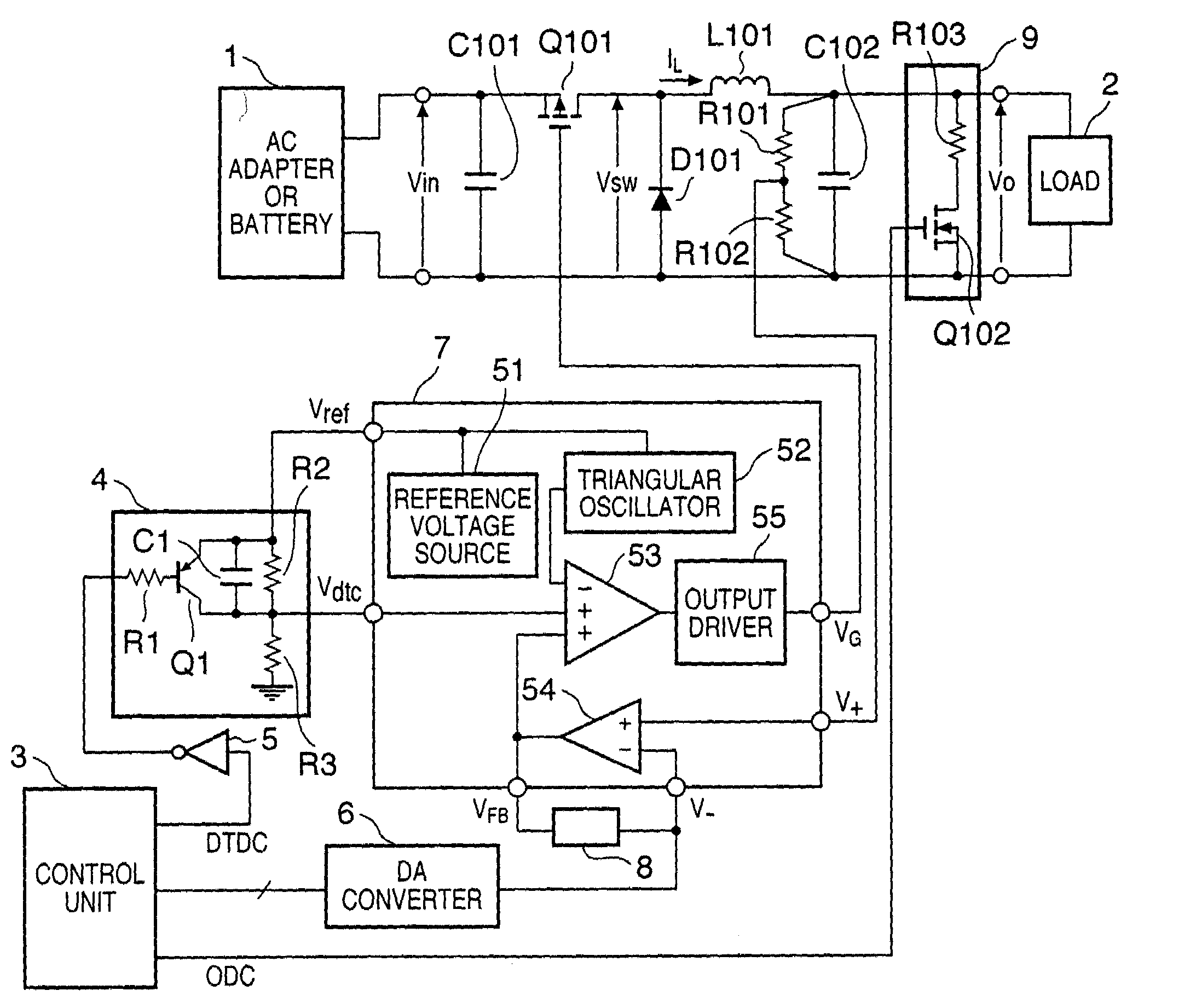
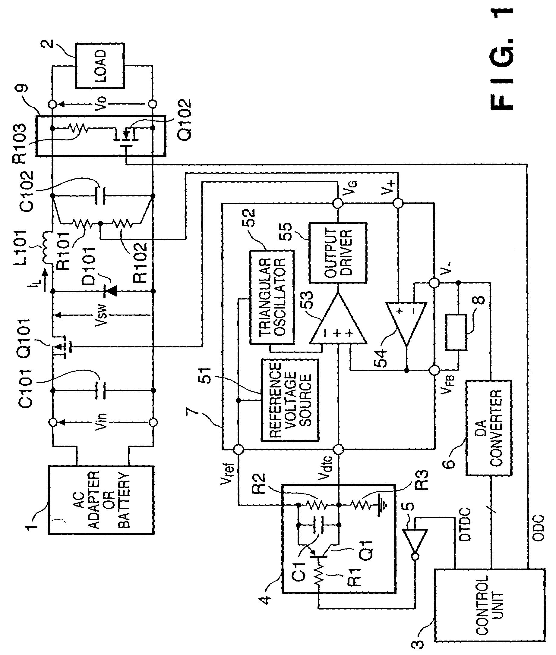
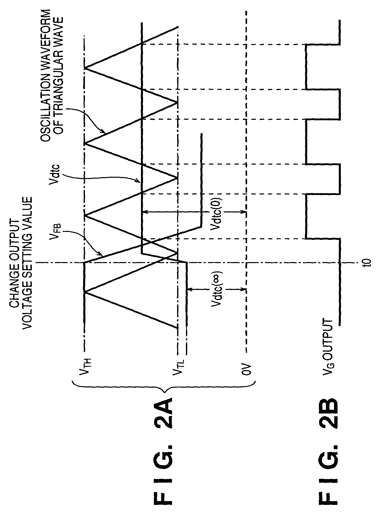
[0084]In this embodiment, when an output voltage setting value Vo(1) is low in the output voltage setting range, a voltage Vdtc(0) of a dead-time control circuit 4 is changed to a high voltage. With this operation, an increase in coil current IL can be limited by the upper limit value of the ON duty in PWM control, thereby reducing an input rush current. In this case, even if the ON duty value in PWM control is kept small, the ON duty in PWM control in the steady state is originally kept low because of a low output voltage. Even if the ON duty is strongly limited, the response time upon a change in voltage is not prolonged, and the time required to cause the output voltage to reach the setting voltage Vo(1) falls within a predetermined time.

[0085]When the output voltage before the change in voltage is high, the ON duty value in PWM control in the steady state is originally large. Unless the maximum ON duty (upper limit value or limit value of the ON duty value) in PWM control is set...

second embodiment

[0098]A DC / DC converter according to the second embodiment of the present invention will be described below. In the following description, portions which are the same as those of the first embodiment will not be described, and the characteristic portions of the second embodiment will be described below.

[0099]In the above first embodiment, the object of the present invention can be achieved. In the second embodiment, a rush current is further reduced, and a time required for causing an output voltage to reach a setting value is reduced. The basic circuit arrangement is the same as in FIG. 1.

[0100]In the present embodiment, it is a feature that in synchronism with a timing at which the setting signal of the output voltage output from a control unit 3 changes, a dead-time control voltage Vdtc(0) changes to obtain an ON duty which corresponds the voltage between the output voltage value before updating and the updated output voltage value.

[0101]In PWM control, the ON duty of a main swit...

third embodiment

[0114]A DC / DC converter according to the third embodiment of the present invention will be described below. In the following description, portions which are the same as those of the first and second embodiments will not be described, and the characteristic portions of the third embodiment will be described below.

[0115]The DC / DC converter described in the first and second embodiments optimizes the operation in increasing an output voltage.

[0116]When reducing the output voltage, especially, when a load current is 0, it is difficult to set an output voltage to a target output voltage within a predetermined time only by adjusting the ON duty of a main switching element Q101. Hence, in the third embodiment, when a setting value Vo(1) of an output voltage from a control unit 3 is lower than a setting value Vo(0) of an output voltage before updating, a discharge circuit 9 for discharging a capacitor C102 connected between output terminals and a capacitor (not shown) arranged on a load devi...


PUM


Abstract

In a power supply device including a PWM-controlled DC / DC converter which changes an output voltage on the basis of a setting signal, and a control unit, the DC / DC converter includes a circuit for changing a dead-time control voltage in accordance with a control signal. A dead-time control circuit is arranged, which sets the ON duty of a PWM main switching element at a predetermined time constant in accordance with the dead-time control voltage. The control unit outputs the setting signal and control signal. In this arrangement, an input rush current generated in changing the output voltage during operation can be reduced, and the time required for causing the output voltage to reach the setting value can also be shortened.

Description

FIELD OF THE INVENTION[0001]The present invention relates to a power supply device and a printing apparatus having the same and, more particularly, to a power supply device used as a power supply for an electronic device and any other device and including a PWM-controlled DC / DC converter which changes an output voltage on the basis of a setting signal, and a printing apparatus having the power supply device.BACKGROUND OF THE INVENTION[0002]A switching DC / DC converter is very popular as a power supply for an electronic device or any other device. A known type of switching DC / DC converter can change or regulate an output voltage in accordance with a setting signal (command) from the control unit of an electronic device or any other external device.[0003]FIG. 10 is a diagram showing the typical circuit arrangement of such a DC / DC converter. The illustrated circuit is a PWM-controlled DC / DC converter. A power supply control IC 7 includes a PWM comparator 53 incorporated in a power suppl...

Claims


Application Information

Patent Timeline
Patent Type & Authority Patents(United States)
IPC IPC(8): G05F1/00H02M1/10H02M3/155H02M1/32
CPCH02M1/32
Inventor MASUDA, KAZUNORI
Owner CANON KK
Why Eureka
Try Eureka