Permalloy bridge with selectable wafer-anistropy using multiple layers

a wafer anistropy and permalloy technology, applied in the field of magnetoresistive materials and magnetoresistivebased sensors, can solve the problems of limited device sensitivity and range of prior art magnetic sensing devices, and achieve the effect of maximizing the magnetic sensitivity of the magnetic sensor, enhancing matching capabilities, and enhancing the matching capability

Active Publication Date: 2007-10-09
HONEYWELL INT INC +1
View PDF6 Cites 9 Cited by
  • Summary
  • Abstract
  • Description
  • Claims
  • Application Information

AI Technical Summary

Benefits of technology

[0011]The aforementioned aspects of the invention and other objectives and advantages can now be achieved as described herein. A magnetic sensing method and apparatus are disclosed. In general, a plurality of bridge circuits can be provided, wherein each bridge circuit among the plurality of bridge circuits is formed on a separate permalloy layer comprising a plurality of permalloy bridge runners. The permalloy bridge runners can be selected such that each permalloy bridge runner possesses a wafer anisotropy perpendicular or any selectable angle to a length of the permalloy bridge runner in order to form a magnetic sensor based on the bridge circuits, maximize the magnetic sensitivity of the magnetic sensor, and independently control the wafer anisotropy through the use of multiple bridge circuits configured on separate permalloy layers.
[0012]Additionally, the bridge circuits can be arranged as concentric bridge circuits. The permalloy bridge runners can be configured to possess said wafer anisotropy at, for example, but not limited to a 45-degree angle thereof to provide enhanced matching capabilities between the bridge circuits. Each bridge circuit can be provided as a Wheatstone bridge circuit.
[0013]By constructing bridges in two or more layers of permalloy, these improvements can be further utilized. Bridges with perpendicular runners can be deposited so that all runners are deposited with the wafer anisotropy perpendicular to the length of the runner, so that each runner's sensitivity is maximized. Also, process limitations on runner spacing can be overcome by placing runners in multiple layers in order to improve the sensitivity. Runners on all layers would not necessarily need to be electrically connected to achieve this benefit.

Problems solved by technology

Prior art magnetic sensing devices have been limited in the range and offering of device sensitivity.

Method used


Image

  • Permalloy bridge with selectable wafer-anistropy using multiple layers
  • Permalloy bridge with selectable wafer-anistropy using multiple layers
  • Permalloy bridge with selectable wafer-anistropy using multiple layers

Examples


Embodiment Construction

[0019]The particular values and configurations discussed in these non-limiting examples can be varied and are cited merely to illustrate at least one embodiment and are not intended to limit the scope of the invention.

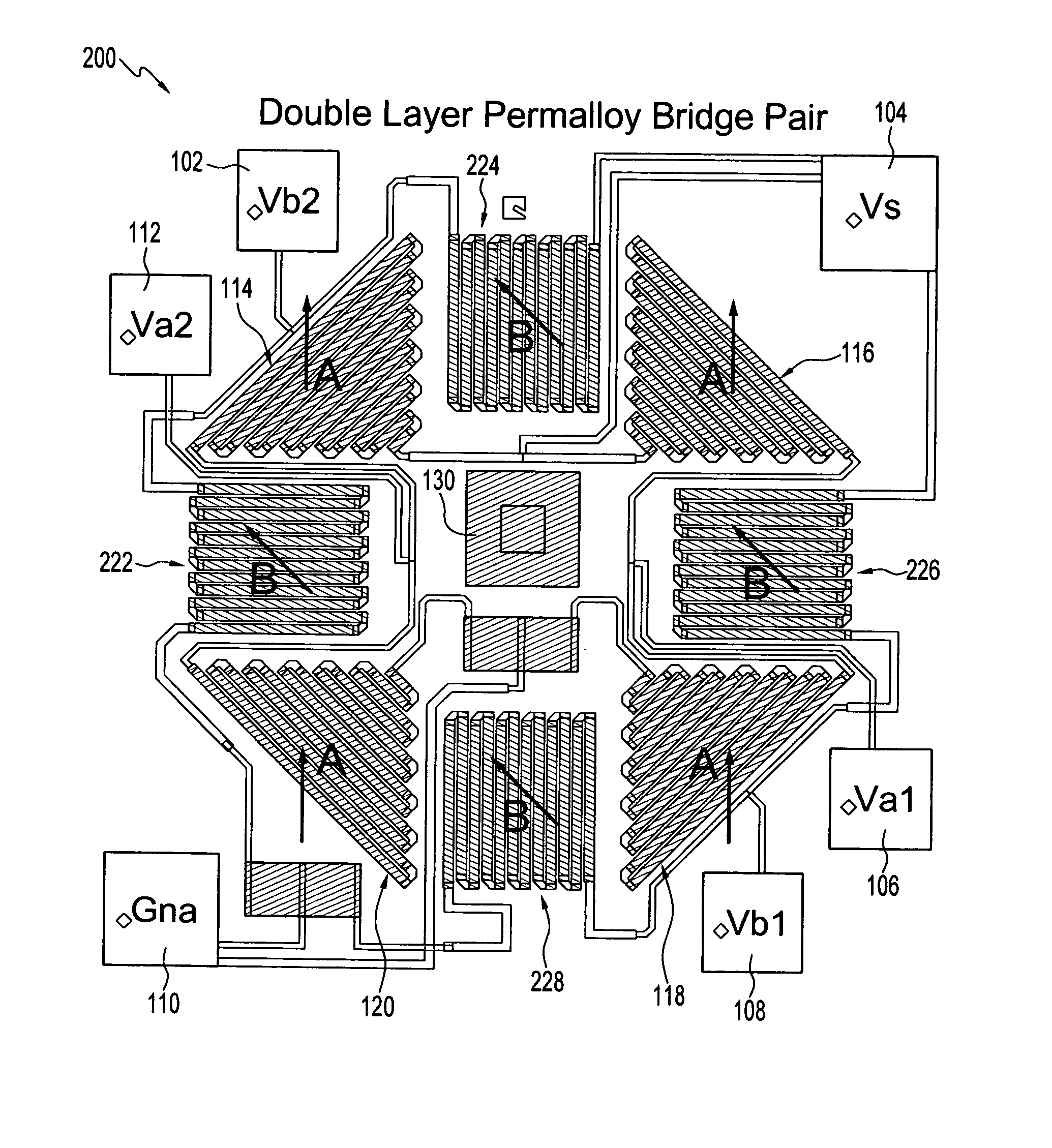
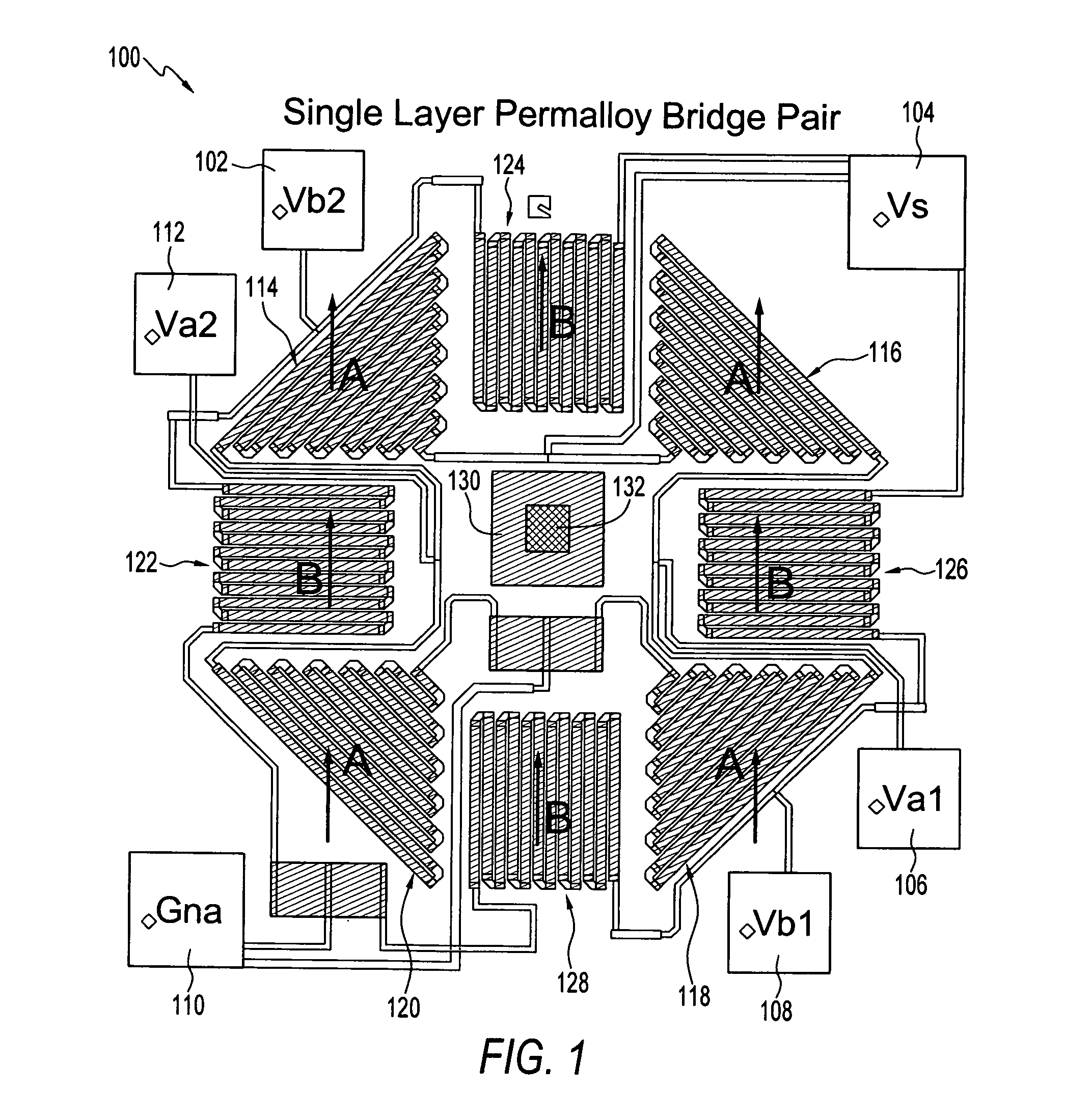
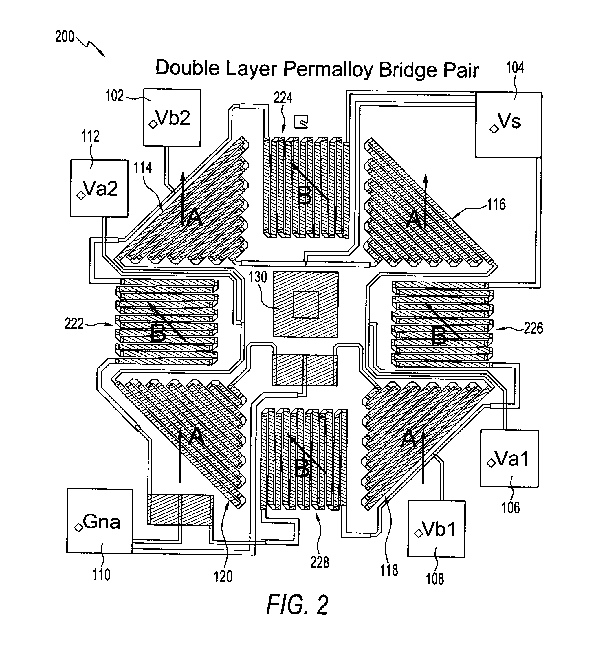
[0020]FIG. 1 illustrates a schematic diagram of a bridge circuit 100 formed from a single layer permalloy bridge pair. Circuit 100 generally includes a circuit bridge A composed of bridge elements 114, 116, 118, and 120, and a circuit bridge B composed of bridge elements 122, 124, 126, and 128. The bridge circuit 100 is connected to a ground pad 110 and voltage pads 112, 102, 104, 106, and 108. Note that a magnet may be located centrally within or proximate to circuit 100. Markers 130 and 132 can be provided as laser alignment markers for offset trimming in the center of circuit 100 with respect or next to the ground pad 110. Although not specifically shown in FIG. 1, it can be appreciated that a magnet can be disposed centrally with respect to bridge circuit 100 and i...


PUM


Abstract

A magnetic sensing method and apparatus include a plurality of bridge circuits, wherein each bridge circuit or element within a bridge is formed on a separate permalloy layer comprising a plurality of permalloy bridge runners. The permalloy bridge runners can be selected such that each permalloy bridge runner possesses a selectable wafer anisotropy to a length of the permalloy bridge runner in order to form a magnetic sensor based on the bridge circuits, maximize the magnetic sensitivity of the magnetic sensor, maximize the matching between bridges and independently control the wafer anisotropy through the use of multiple bridge circuits configured on separate permalloy layers.

Description

TECHNICAL FIELD[0001]Embodiments are generally related to magnetic sensors. Embodiments are also related to magnetoresistive materials and magnetoresistive-based sensors. Embodiments are additionally related to permalloy materials and magnetic sensors which incorporate such permalloy materials.BACKGROUND[0002]Magnetoresistors are often utilized for the contactless detection of changes in state, such as the measurement of an angular position of a rotatably mounted part. Magnetoresistive-based sensors typically include magnetic field-dependent resistors, which are arranged in a bridge circuit configuration and through which a control current is fed. When a magnetoresistive-based sensor is influenced by a magnetic field, a voltage can be established in which the magnitude of the voltage depends on the magnitude and direction of the magnetic field associated with the sensor.[0003]The relationship between an associated bridge circuit voltage and the magnetic field direction can be utiliz...

Claims


Application Information

Patent Timeline
Patent Type & Authority Patents(United States)
IPC IPC(8): G01R33/02
CPCB82Y25/00G01R33/093G01R33/09
Inventor CHILCOTE, JASON M.HOLMAN, PERRY A.REHN, LARRY A.
Owner HONEYWELL INT INC
Why Eureka
Try Eureka